

Hydraulic fluid coupling
- Summary
- Abstract
- Description
- Claims
- Application Information
AI Technical Summary
Benefits of technology
Problems solved by technology
Method used
Image

Examples
Embodiment Construction
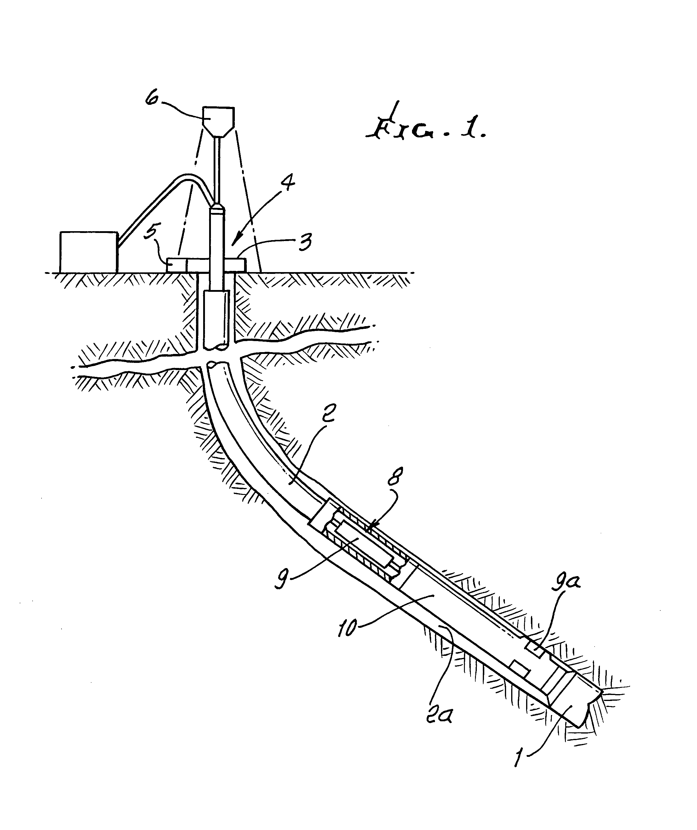
[0022]FIG. 1 shows diagrammatically a typical rotary drilling installation of a type in which the present invention may be used. The bottom hole assembly includes a drill bit 1 connected to the lower end of drill string 2 which is rotatably driven from the surface by a rotary table 3 on a drilling platform 4. A suitable drilling fluid, generally referred to as mud, is pumped downward through the interior of the drill string 2 to assist in drilling and to flush cuttings from the drilling operation back to the surface in the annular hole 2a outside of the drill string 2. The rotary table is driven by a drive motor 5. Raising and lowering of the drill string, and application of weight-on-bit, is under the control of draw works indicated diagrammatically at 6.
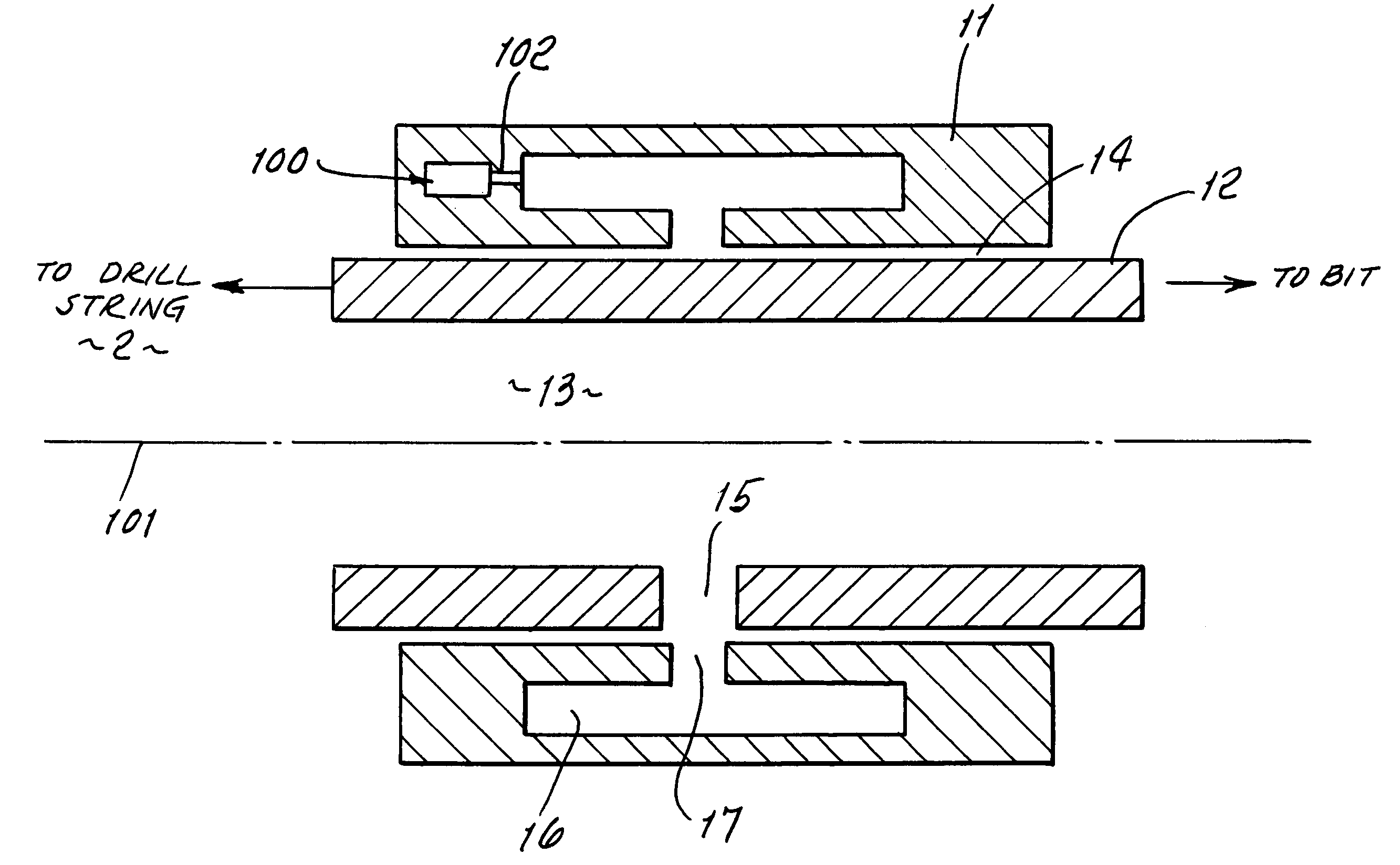
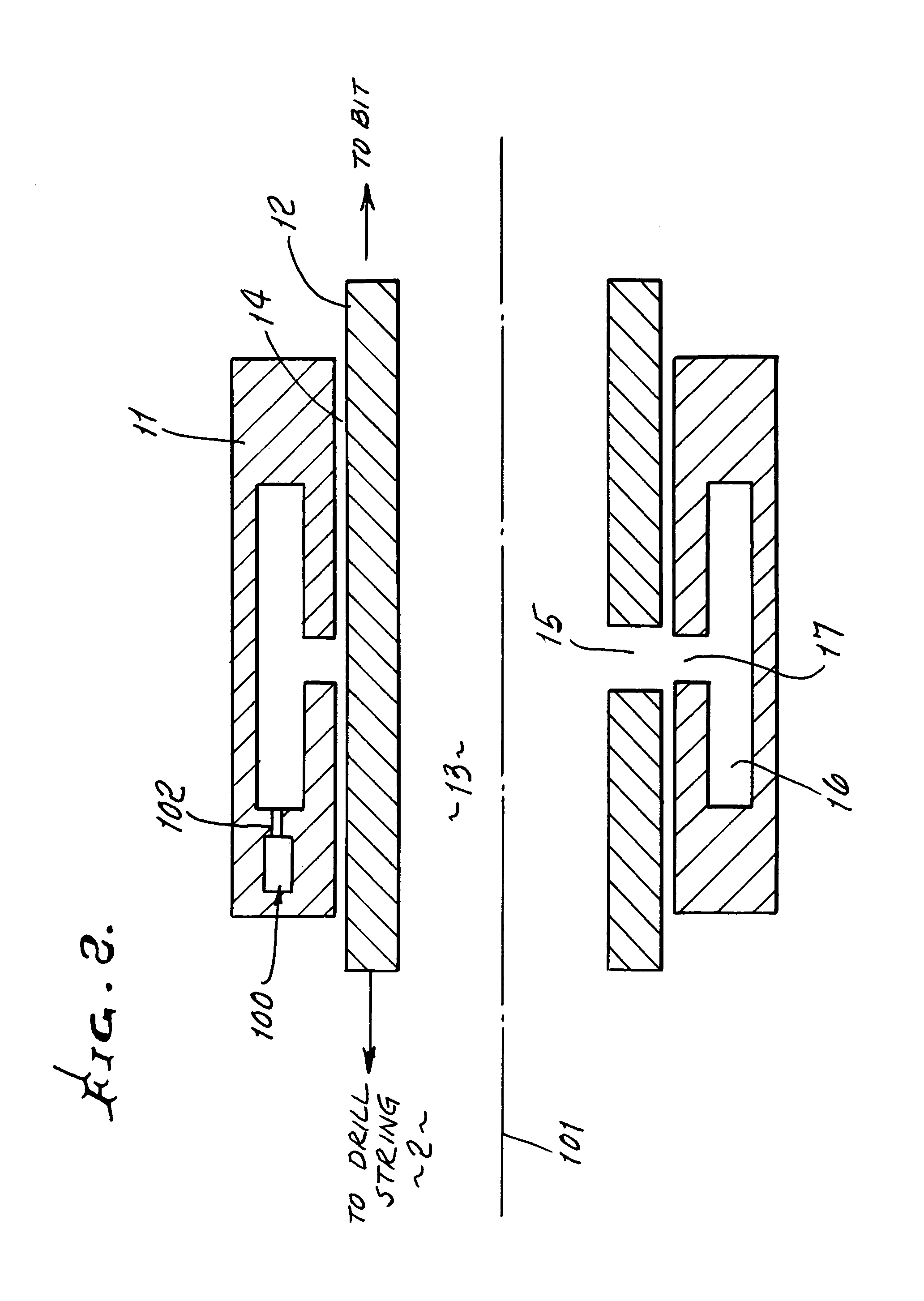
[0023]The bottom hole assembly includes a bearing section 8 for attachment to the drill string 2, and that permits rotary motion between the drill string 2 and the steerable section 9. The outer surface 10 of the steerable section ...
PUM
 Abstract
Description
Claims
Application Information