Light emitting diode illumination apparatus

a technology of light-emitting diodes and illumination apparatuses, which is applied in lighting and heating apparatuses, semiconductor devices for light sources, and connection of coupling devices, etc., can solve the problems of large amount of radiated heat, low light-emitting performance, and inapplicability of tungsten light bulbs in the area, so as to achieve the effect of effectively dispersing heat sources and maintaining the light-emitting efficiency of each light-emitting diod

Active Publication Date: 2007-06-05
TAIWAN OASIS TECH CO LTD
View PDF3 Cites 283 Cited by
  • Summary
  • Abstract
  • Description
  • Claims
  • Application Information

AI Technical Summary

Benefits of technology

[0007]The primary objective of the present invention is to provide a light emitting diode illuminating apparatus that uses a heat dissipating device and a substrate in contact with each other under normal conditions to conduct a heat source from the substrate to the heat dissipating device and effectively disperse the heat source from the heat dissipating device, so as to maintain the light emitting efficiency of each light emitting diode.

Problems solved by technology

Tungsten light bulbs and mercury lamps are common traditional illumination apparatus, and the tungsten light bulb converts a vast majority of electric energy into radiated heat during the light emitting process of the tungsten light bulb, and thus the light emitting performance is not high, but the quantity of radiated heat is large.
Therefore, the tungsten light bulb is not applicable in the areas with a hotter climate.
As to the mercury lamp, although it has a better light emitting performance than the tungsten light bulb, the mercury coated on the internal walls of the lamp causes environmental pollutions when the lamp is dumped.
Such light emitting diode light bulbs usually cannot be operated in normal conditions and usually has a high failure rate.

Method used


Image

  • Light emitting diode illumination apparatus
  • Light emitting diode illumination apparatus
  • Light emitting diode illumination apparatus

Examples


Embodiment Construction

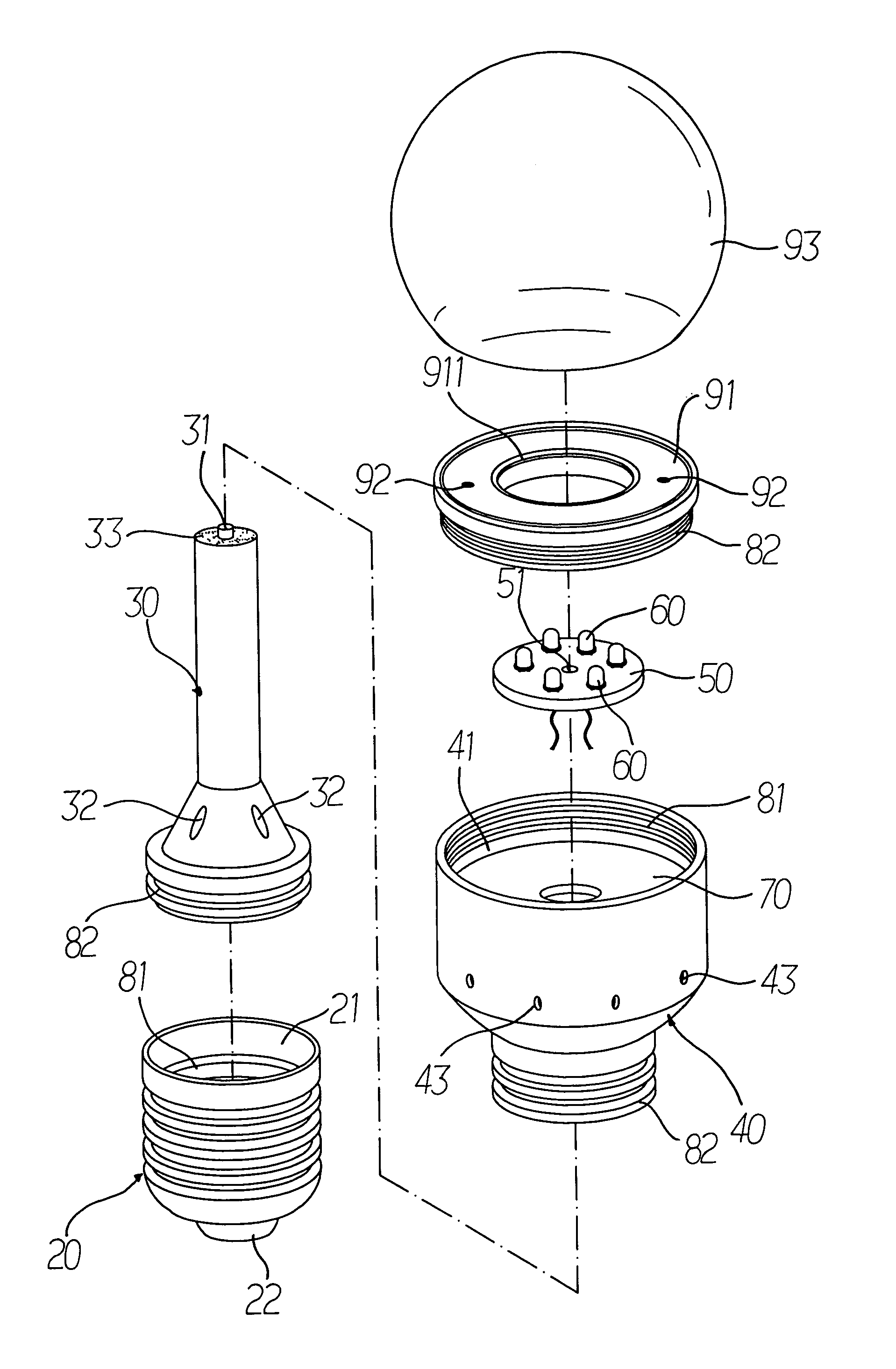
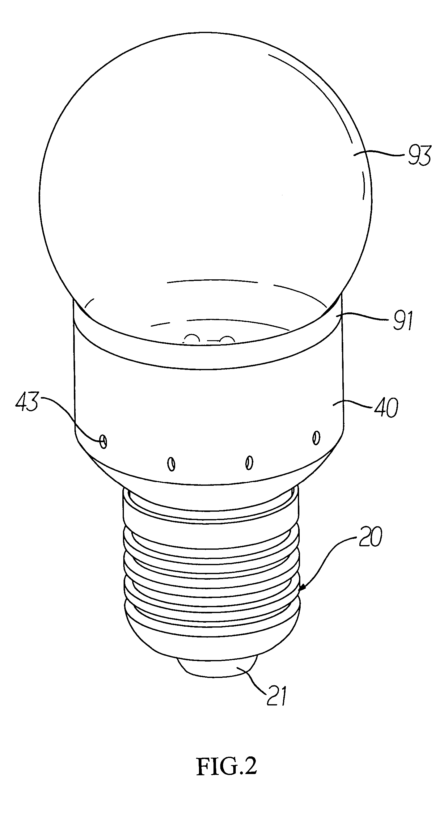
[0013]Referring to FIGS. 2 and 3, a basic structural assembly of a light emitting diode illumination apparatus of the present invention comprises:

[0014]a light bulb base 20, having a groove base 21 for installing different components and a connector 22 disposed at the bottom for electrically connecting an external circuit, and the groove base 21 has an internal thread 81 for securing a heat dissipating device 30 and a plastic lid 40 onto the groove base 21 in sequence;

[0015]a heat dissipating device 30, having an end coupled into the groove base 21 of the light bulb base 20, and the heat dissipating device 30 has an external thread 82 corresponding to the internal thread 81 in the groove base 21, and the other end being contacted with a metal substrate 50 through a thermal conductive grease under normal conditions, and the contact surface of the heat dissipating device 30 and the metal substrate 50 can be engaged with the fixing pillar 31 and the fixing groove 51 according to the pr...


PUM


Abstract

The present invention describes a light emitting diode illumination apparatus made of a light bulb base, a heat dissipating device, a plastic lid, a drive substrate, a metal substrate, a circular insulated base and a casing, and the heat dissipating device is in contact with the metal substrate in normal conditions, such that the heat source produced by each light emitting diode is conducted to the heat dissipating device through the metal substrate and then conducted from the heat dissipating device to the light bulb base for effectively dispersing the heat source and maintaining the light emitting efficiency of each light emitting diode.

Description

BACKGROUND OF THE INVENTION[0001]1. Field of the Invention[0002]The present invention relates to an illumination apparatus that uses a light emitting diode as a light source, more particularly to a light emitting diode illumination apparatus that can effectively disperse the heat produced by the heat source of the light emitting diode illumination apparatus.[0003]2. Description of the Related Art[0004]As illumination apparatus is an indispensable item for our daily life, and the requirements for modernization and life quality are different, the level of requiring illumination apparatus varies. Tungsten light bulbs and mercury lamps are common traditional illumination apparatus, and the tungsten light bulb converts a vast majority of electric energy into radiated heat during the light emitting process of the tungsten light bulb, and thus the light emitting performance is not high, but the quantity of radiated heat is large. Therefore, the tungsten light bulb is not applicable in the ...

Claims


Application Information

Patent Timeline
Patent Type & Authority Patents(United States)
IPC IPC(8): F21V29/00
CPCF21K9/135F21V3/00F21V19/003F21V29/89F21V23/006F21V29/78F21V29/83F21V19/0035F21Y2101/02Y10S362/80F21Y2103/022F21K9/232F21K9/238F21Y2103/33F21Y2115/10
Inventor LEE, MING-SHUNSUNG, PING-RU
Owner TAIWAN OASIS TECH CO LTD
Why Eureka
Try Eureka