Method and device for hill start

a technology of a start device and a hill start, which is applied in the direction of brake systems, machines/engines, gearing, etc., can solve the problems of difficult or impossible for the driver to know precisely how a certain system works, near accidents, and low reliability

Active Publication Date: 2007-06-05
VOLVO LASTVAGNAR AB
View PDF13 Cites 59 Cited by
  • Summary
  • Abstract
  • Description
  • Claims
  • Application Information

AI Technical Summary

Benefits of technology

[0034]In this way, the high efficiency and durability of the stage-geared gearbox can be combined with the user-friendliness of the automatic gearbox, while at the same time providing a simple and safe hill start-up function. The invention results in reduced loading in the clutch, and moreover, the starting sequence is carried out in a shorter time. For example, a speed of roughly two kilometers per hour in the wrong direction doubles the clutch loading, compared with starting from stationary. Another advantage of the invention is that the application speed of the clutch can be reduced so that torque transients in the drive line are avoided as the vehicle is held stationary with the aid of the hill start function. The invention does not use predetermined fixed (engine torque) levels or predetermined times for releasing the service brake, but adapts to traveling resistance on the concerned hill and the fact that the time in order to achieve the abovementioned minimum driving torque varies on account of driver conduct, engine dynamics, turbo dynamics, and the losses in engine-driven units. The procedure is not possible without external application of the service brakes.
is that the application speed of the clutch can be reduced so that torque transients in the drive line are avoided as the vehicle is held stationary with the aid of the hill start function. The invention does not use predetermined fixed (engine torque) levels or predetermined times for releasing the service brake, but adapts to traveling resistance on the concerned hill and the fact that the time in order to achieve the abovementioned minimum driving torque varies on account of driver conduct, engine dynamics, turbo dynamics, and the losses in engine-driven units. The procedure is not possible without external application of the service brakes.

Problems solved by technology

As the systems are complex, it is difficult or impossible for the driver to know precisely how a certain system functions in a given situation.
This may to occasions in which the system functions in a way that is not expected by the driver and could result in near accidents.
Moreover, the great complexity of the systems described means that the reliability is lower than for a system that does not require a large number of external components.
As an example, a fault on one of the included components can result in the system becoming unserviceable.
Another disadvantage of the described systems is that the extra sensors add unnecessary cost to the selling price of the vehicle.
Another problem with the proposed systems is that it is possible to use them as a parking brake.
If something should happen when the vehicle is parked in this way, the vehicle may lose braking capacity altogether.
The vehicle may, for example, start to roll in an uncontrolled manner with serious damage as a consequence.
This may happen if, for example, the driver is delayed and / or the brake system loses pressure more quickly than expected, for example if a component is slightly leaky.
A disadvantage of this system is the relatively poor efficiency of the torque converter included in the transmission.
The solution functions in an intuitive way for the driver, which means that the driver is not surprised by the performance of the system with the result that a near-accident occurs.

Method used


Image

  • Method and device for hill start
  • Method and device for hill start
  • Method and device for hill start

Examples


Embodiment Construction

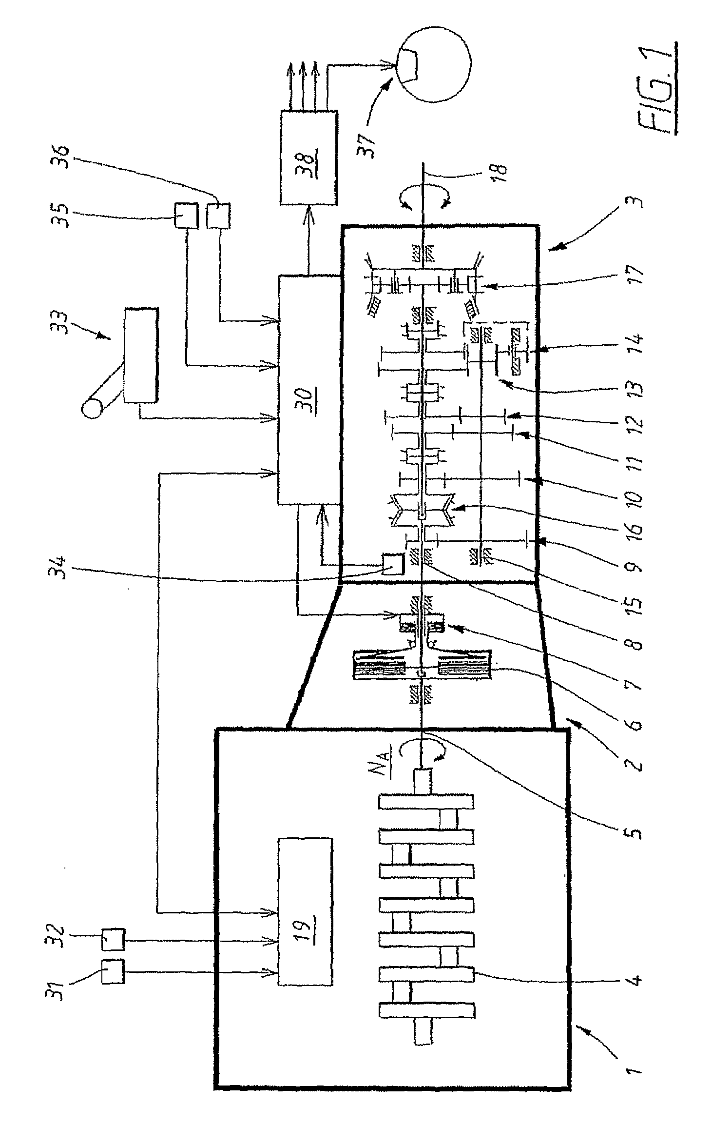
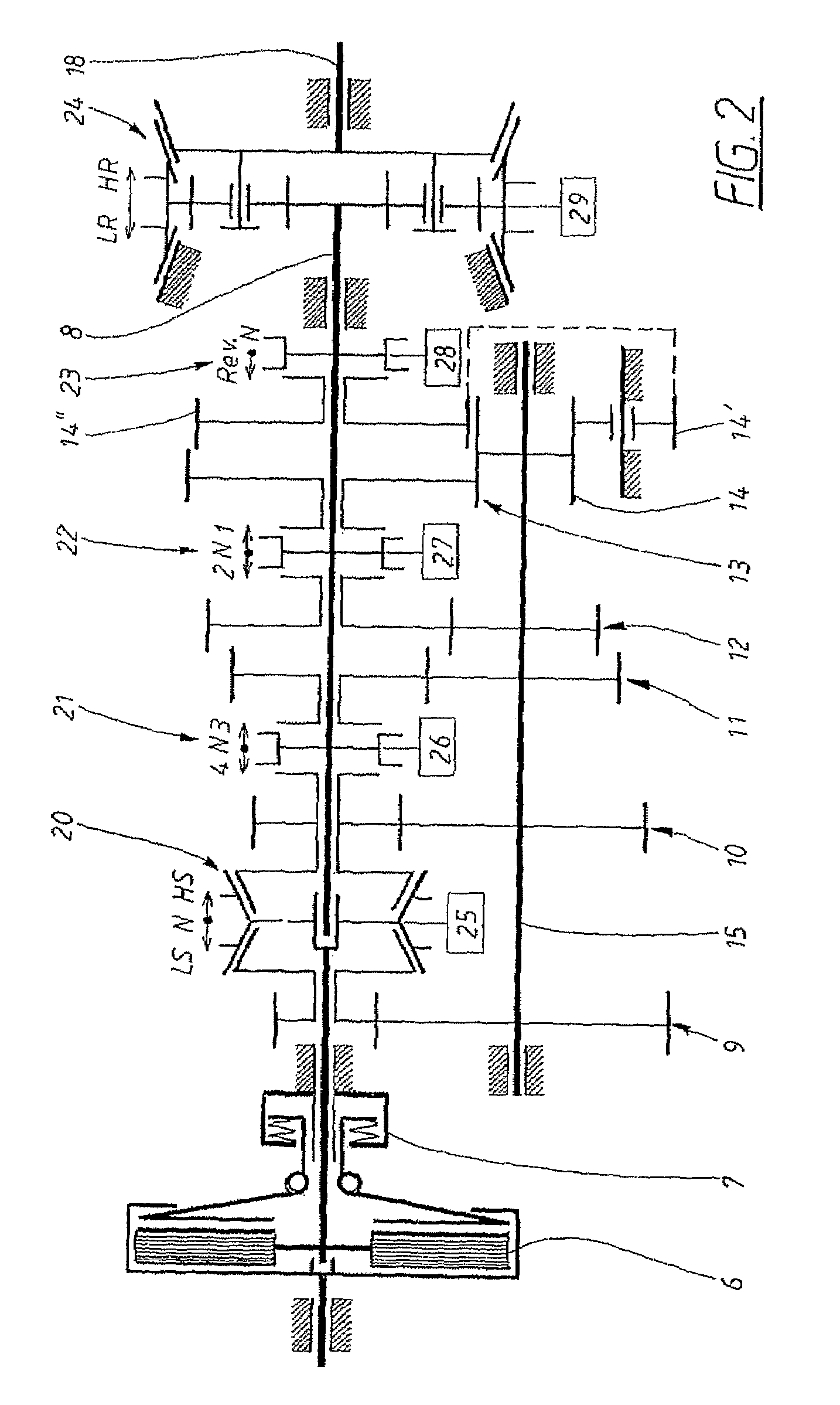
[0039]FIG. 1 shows a schematic representation of the device according to an embodiment of the invention. The device comprises an engine 1, a clutch device 2 and a stage-geared automated gearbox 3. The engine exemplarily comprises a crankshaft 4 and an output shaft 5 provided with a flywheel (not shown in the figure) that is coupled to a single-plate dry disk clutch 6. The clutch is provided with a pneumatic piston / cylinder device 7, by means of which the clutch can be engaged and disengaged. The gearbox comprises an input shaft 8 which, via a number of gearwheel pairs 9, 10, 11, 12, 13, can drive an intermediate shaft 15. The gearwheel pairs 10, 11, 12, 13 represent four unsynchronized forward gears, and the gearwheel arrangement 14, 14′, 14″, with three gearwheels represents a reverse gear. In addition, the gearbox comprises a synchronized split gear 16 with a low gear stage LS and a high gear stage HS and also what is known as a range gear 17 for shifting between low range LR and ...


PUM


Abstract

Method and arrangement for facilitating hill-starting of a stationary motor vehicle. The method includes applying at least one braking device using a brake pedal and estimating the traveling resistance of the vehicle using a control unit (30). The control unit (30) determines a starting gear, a starting torque and a starting speed with regard to the estimated traveling resistance. The driver releases the brake pedal and the brakes are kept applied for a certain time. The driver operates an accelerator pedal to a position at least corresponding to the minimum transmitted torque and a clutch device (2) for a gearbox (3) is activated by the control unit (30) when the starting speed has been achieved. The control unit (30) releases the braking devices as a function of the increase in the transmitted driving torque of the clutch.

Description

CROSS REFERENCE TO RELATED APPLICATIONS [0001]The present application is a continuation patent application of International Application No. PCT / SE2003 / 002042 filed 18 Dec. 2003 now abandoned, which was published in English pursuant to Article 21(2) of the Patent Cooperation Treaty, and which claims priority to Swedish Application No. 0203903-0 filed 30 Dec. 2002. Said applications are expressly incorporated herein by reference in their entireties.TECHNICAL FIELD[0002]The present invention relates to a method for facilitating hill-starting (start-up on a hill) of a stationary vehicle, and a device for implementing the method.BACKGROUND OF THE INVENTION[0003]When a vehicle is stationary on an uphill slope and is to start driving again without rolling backward, it is usual for the driver to hold the vehicle stationary using the handbrake and the footbrake. When the driver is to start driving, he or she then moves the foot from the brake pedal to the accelerator pedal. In order that the...

Claims


Application Information

Patent Timeline
Patent Type & Authority Patents(United States)
IPC IPC(8): B60T7/12B60W10/04B60W30/18
CPCB60T7/122B60W30/18027B60W30/18118B60T2201/06B60W10/02B60W10/06Y10T477/87F16H37/046Y10S477/901Y10S477/90Y10T477/847Y10T477/816
Inventor STEEN, MARCUSLAURI, ERIKKARLSSON, LARS
Owner VOLVO LASTVAGNAR AB
Why Eureka
Try Eureka