Turbocharging apparatuses and vehicles using the same

Inactive Publication Date: 2014-04-17
SHANXI HUAQI WIND ENERGY TECH
View PDF5 Cites 1 Cited by
  • Summary
  • Abstract
  • Description
  • Claims
  • Application Information

AI Technical Summary

Benefits of technology

[0007]In the turbocharging apparatus according to the present invention and vehicles using such turbocharging apparatus, the impeller is propelled by the flow of air (wind power) generated when the vehicle travels. Since the turbocharging apparatus according to the present invention uses normal-temperature fresh air flow for propulsion, the turbocharger remains in a normal-temperature operation state all the time. Hence, the turbocharging apparatus according to the present invention may be

Problems solved by technology

Automobile turbocharging systems used in the global vehicle industry are chiefly classified into four major classes: mechanical turbocharging, exhaust gas turbocharging, pressure wave supercharging and electronic turbocharging, wherein the pressure wave supercharging is not adapted to be mounted on a car due to great heaviness and large noise, and the electronic turbo charging is not well accepted by this industry due to consumption of electrical energy of a generator, generation of too small wind pressure and failure to improve engine performance.
It also consumes engine power and the supercharging efficiency is not high.
However, this technology also has apparent drawbacks: one drawback is high production cost and maintenance cost so that ordinary consumers cannot afford; and a second drawback is low

Method used


Image

  • Turbocharging apparatuses and vehicles using the same
  • Turbocharging apparatuses and vehicles using the same
  • Turbocharging apparatuses and vehicles using the same

Examples


Embodiment Construction

[0026]Hereunder, the turbocharging apparatus and the vehicle using the turbocharging apparatus according to the present invention will be described in detail with reference to the figures. In the present invention, the vehicle is a vehicle using an internal combustion engine as a motive power, including but not limited to the automobiles described below as examples only.

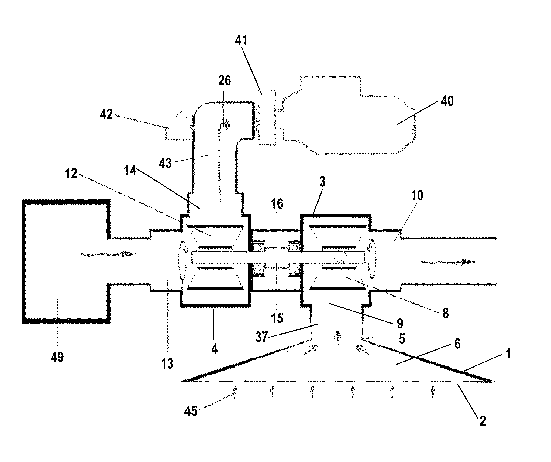
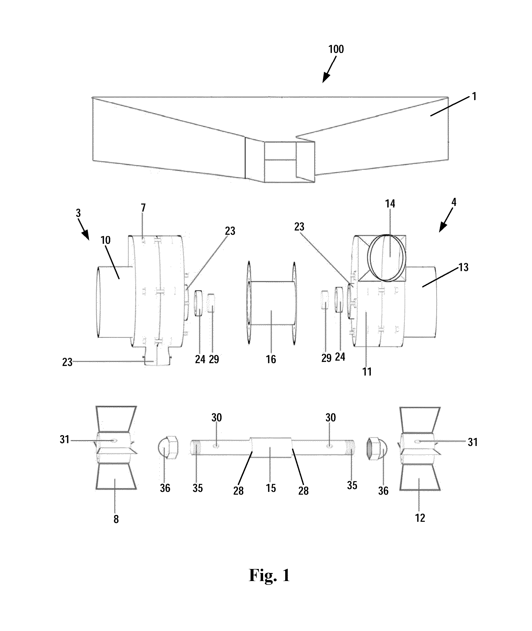
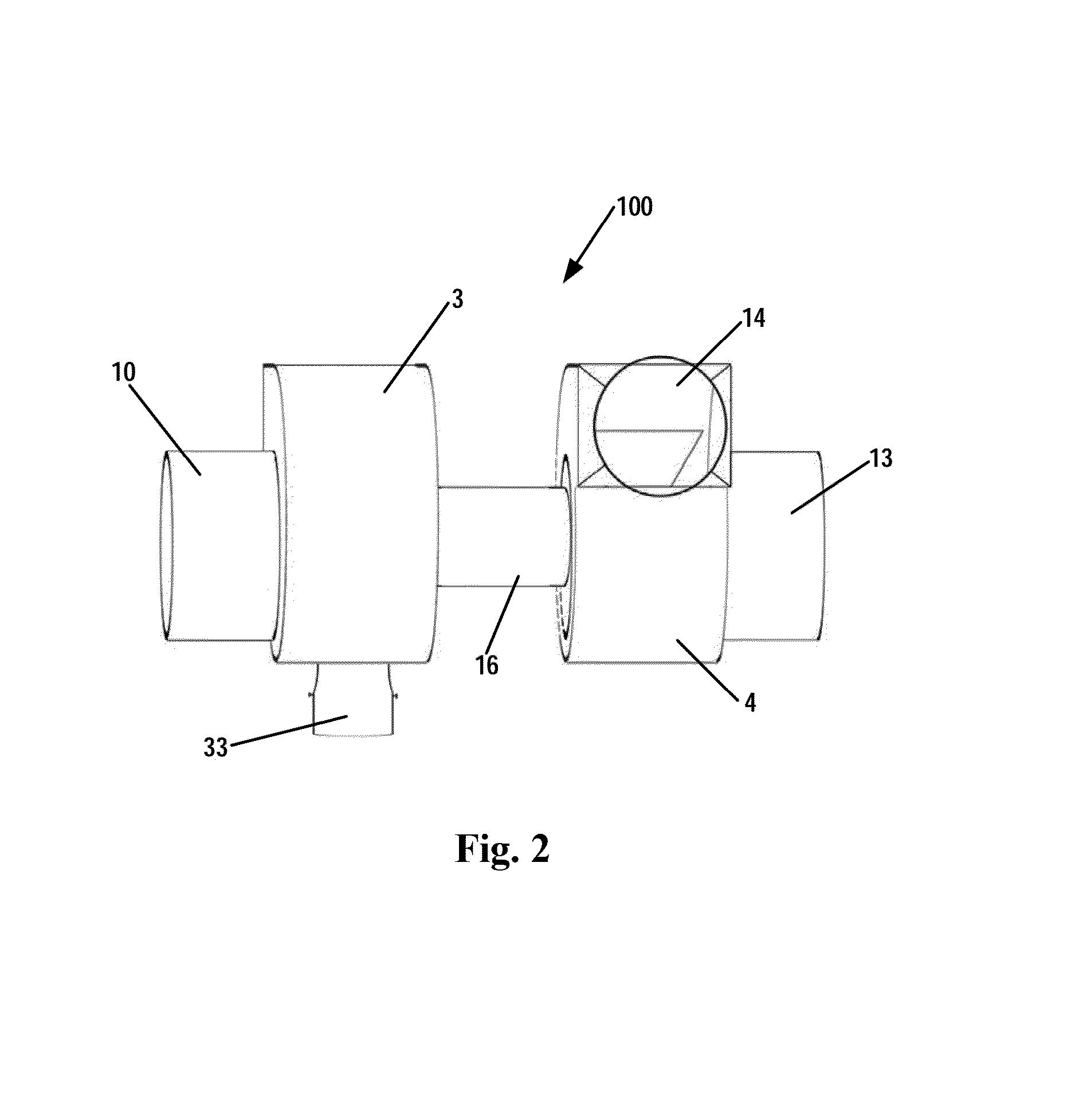
[0027]Reference is made to FIG. 1 and FIG. 2. FIG. 1 is an exploded view of general construction of a turbocharging apparatus according to an embodiment of the present invention. FIG. 2 is a schematic view illustrating an assembled turbocharging apparatus. As shown, the turbocharging apparatus is generally designated by the reference number “100”. The turbocharging apparatus 100 according to the present invention comprises a wind collecting device (not shown in FIG. 2), a first turbine 3 and a second turbine 4.

[0028]Referring to FIGS. 1, and 14-18, the wind collecting device 1 is generally barrel-shaped and may be in...


PUM


Abstract

There is provided a turbocharging apparatus and vehicles using the same. The turbocharging apparatus comprises a wind collecting device, a first turbine and a second turbine. The wind collecting device comprises a first opening and a second opening and an air flow channel for connecting the two openings. A cross-sectional area of the air flow channel decreases as the air flow channel extends from the first opening towards the second opening. The first turbine comprises a first turbine housing, a first impeller rotatably located in the first turbine housing, a wind inlet communicated with the second opening, and a wind outlet. The second turbine comprises a second turbine housing, a second impeller rotatably located in the second turbine housing, an air suction inlet and an air outlet communicated with a throttle valve of the internal combustion engine. The second impeller can, driven by the first impeller, rotate along with the first impeller. The turbocharging apparatus according to the present invention relies on normal-temperature gas flow as a motive power source, substantially reduces production costs and maintenance costs, and meanwhile better ensures stability, high efficiency and durability of the turbocharger.

Description

FIELD OF THE INVENTION[0001]The present invention relates to a turbocharging apparatus, particularly to a turbocharging apparatus for use in vehicles such as automobiles using an internal combustion engine. The present invention further relates to vehicles using such a turbocharging apparatus.BACKGROUND OF THE INVENTION[0002]Automobile turbocharging systems used in the global vehicle industry are chiefly classified into four major classes: mechanical turbocharging, exhaust gas turbocharging, pressure wave supercharging and electronic turbocharging, wherein the pressure wave supercharging is not adapted to be mounted on a car due to great heaviness and large noise, and the electronic turbo charging is not well accepted by this industry due to consumption of electrical energy of a generator, generation of too small wind pressure and failure to improve engine performance. The currently popular automobile turbochargers mainly refer to the mechanical turbocharger and exhaust gas turbocha...

Claims


Application Information

Patent Timeline
IPC IPC(8): F02B33/40
CPCF02B33/40F02B39/08F02C6/12F02M35/10013F02M35/10118F02M35/161F05B2240/941F05D2220/40F05D2220/62F05D2250/511Y02T10/12
Inventor HUANG, JINLIN
Owner SHANXI HUAQI WIND ENERGY TECH
Why Eureka
Try Eureka