
Mode detection and safety monitoring in blood pressure measurement

a blood pressure measurement and mode detection technology, applied in the field of blood pressure monitoring devices, can solve problems such as the possibility of incorrect cuffs

Active Publication Date: 2007-06-05
WELCH ALLYN INC
View PDF15 Cites 31 Cited by
  • Summary
  • Abstract
  • Description
  • Claims
  • Application Information

AI Technical Summary

Benefits of technology

The present invention provides a method for ensuring that blood pressure measurements in neonates are only performed using a suitable cuff and the proper blood pressure measurement procedure. The method can automatically identify the mode of the blood pressure measurement procedure based on the cuff configuration and the pressure sensed during inflation of the cuff. This ensures that the correct blood pressure measurement procedure is used and prevents mistaken application of a non-neonatal procedure. The method can also distinguish between different neonatal procedures and non-neonatal procedures. This helps to protect the neonatal population and ensures accurate blood pressure measurement.

Problems solved by technology

Therefore, the potential exists for an incorrect cuff to be inadvertently connected to an automatic blood pressure measurement device that is an improper cuff type may be connected with respect to the patient whose blood pressure is to be measured.

Method used


Image

  • Mode detection and safety monitoring in blood pressure measurement
  • Mode detection and safety monitoring in blood pressure measurement
  • Mode detection and safety monitoring in blood pressure measurement

Examples


Embodiment Construction

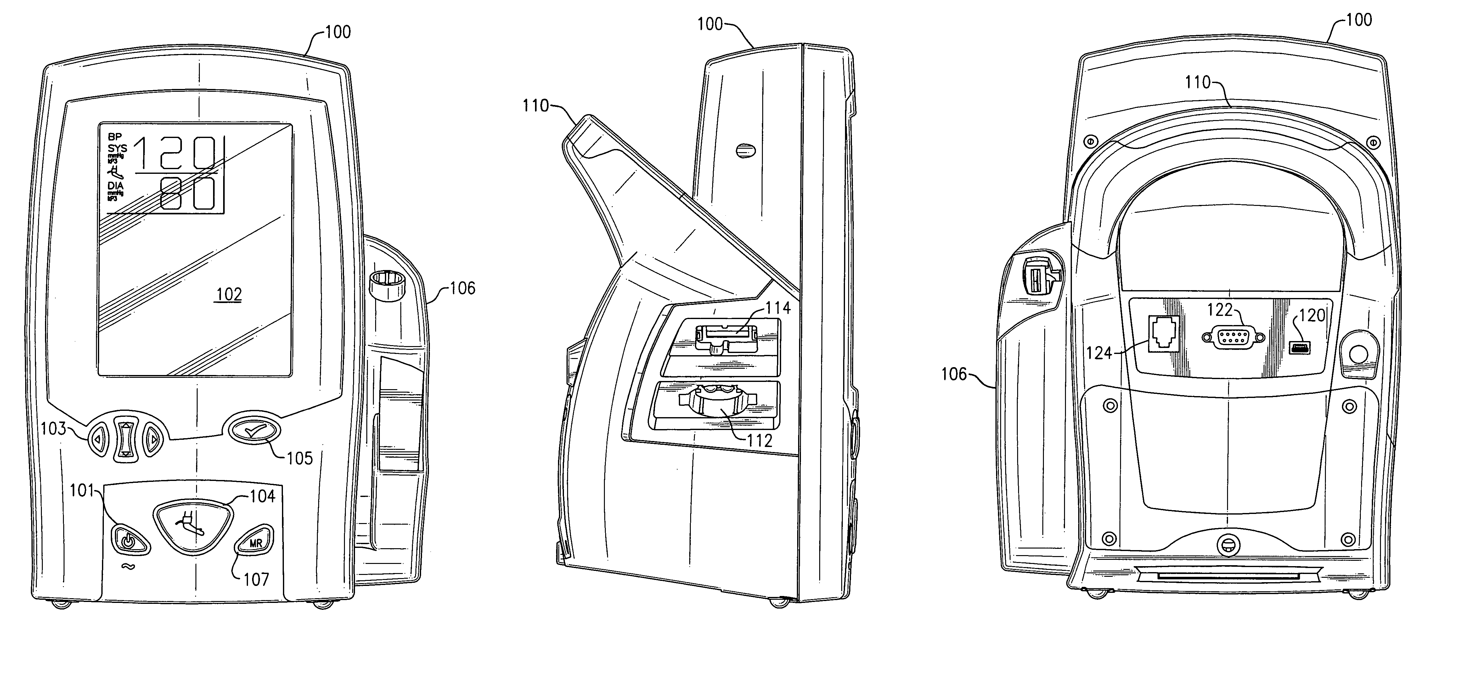
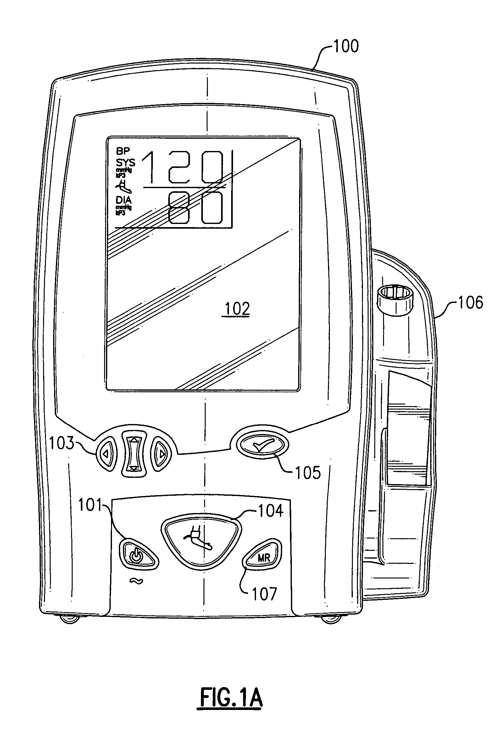
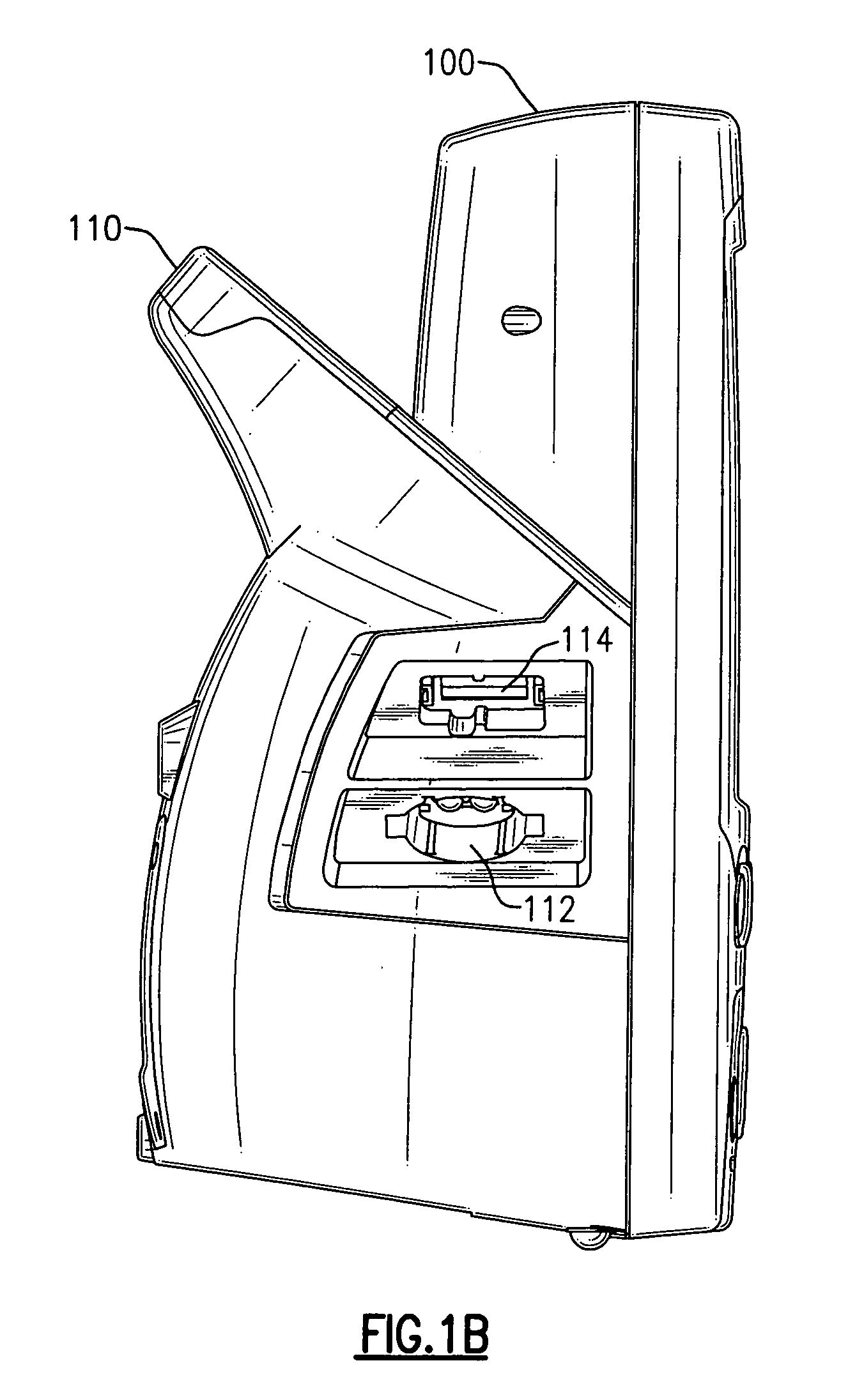
[0038]The present invention will be described herein with reference to an exemplary embodiment of a portable vital signs measurement apparatus 100 depicted in FIGS. 1A through 1C. It is to be understood, however, that the exemplary embodiment the portable vital signs measurement apparatus depicted in FIGS. 1A through 1C is illustrative and not limiting of the present invention. Those skilled in the art will recognize that the present invention may be applied to other embodiments of blood pressure monitoring devices.

[0039]Referring now to the drawings, and FIGS. 1A through 1C in particular, there is depicted therein a portable vital signs measurement apparatus including a connector 112 for connection to a blood pressure cuff for measuring at least one of the diastolic and systolic blood pressures of a patient wearing the blood pressure cuff connected to connector 112. In the exemplary embodiment depicted in FIGS. 1A through 1B, the vital signs measurement apparatus 100 a display 102,...


PUM


Abstract

A method is provided for blood pressure measurement by means of an inflatable cuff (50) applied to a limb of a vertebrate and pneumatically coupled to a first port (112A) and a second port (112B) of a blood pressure measurement apparatus (100). A pump (160) coupled to the second port inflates the cuff pneumatically. During an initial cuff inflation period, a first pressure sensor (180) pneumatically coupled to the first port senses a first pressure and a second pressure sensor (182) pneumatically coupled to the second port senses a second pressure. An analysis module (142) compares the magnitude of the first pressure to the magnitude of the second pressure to determine the relative relationship between the respective magnitudes of the first pressure and the second pressure. The relative relationship between these pressure may be used to determine whether a single lumen or dual lumen cuff is use, to determine whether the blood pressure measurement procedure selected is correct for the cuff actually in use, or to automatically select the proper blood pressure measurement procedure to be used for the actual cuff in use.

Description

CROSS-REFERENCE TO RELATED APPLICATIONS[0001]This application is related to co-pending U.S. patent application Ser. No. 10 / 619,380, filed Jul. 14, 2003, entitled “Motion Management in a Blood Pressure Measurement Device,” published Feb. 10, 2005, as Patent Application Publication No. US2005 / 0033188A1, and subject to assignment to the common assignee of the present application, which application is incorporated herein by reference in its entirety. This application is also related to co-pending U.S. patent application Ser. No. 11 / 032,625, filed Jan. 10, 2005, entitled “A Portable Vital Signs Measurement Instrument and Method of Use Thereof,” and subject to assignment to the common assignee of the present application, which application is incorporated herein by reference in its entirety.FIELD OF THE INVENTION[0002]The present relates generally to blood pressure monitoring devices and, more particularly, to a method for the identification of the cuff type connected to a blood pressure m...

Claims


Application Information

Patent Timeline
Patent Type & Authority Patents(United States)
IPC IPC(8): A61B5/02
CPCA61B5/0225
Inventor LANE, JOHN A.QUINN, DAVID E.MEYERSON, CRAIG M.WHITAKER, TYSON B.
Owner WELCH ALLYN INC
Learn More