Integrated method for release and passivation of MEMS structures

a technology of mems and passivation, applied in the direction of microstructural devices, microstructures, coatings, etc., can solve the problems of stiction being the number one yield-limiting problem, low yield in the fabrication of mems devices, and deformation of the membrane or diaphragm from its intended position, so as to speed up the rate of oxidation and prevent undesirable etching

Inactive Publication Date: 2005-06-07
APPLIED MATERIALS INC
View PDF22 Cites 88 Cited by
  • Summary
  • Abstract
  • Description
  • Claims
  • Application Information

AI Technical Summary

Benefits of technology

[0013]Typically, the plasma used to treat the MEMS structure surfaces is an externally generated plasma. The use of an external plasma generation source provides the ability to control the plasma to exhibit a low, yet uniform, ion density, preventing undesirable etching and / or ion bombardment of the MEMS structure surface during oxidation of the surface. The plasma pretreatment process of the invention is a very gentle, isotropic process which is performed for the sole purpose of preparing the surface for reaction with a SAM precursor. The surfaces may be silicon-containing surfaces or other surfaces within a MEMS structure, including, but not limited to, oxidizable metal-containing surfaces. The highly isotropic process allows all exposed surfaces of the MEMS structure to be contacted with the plasma.
[0014]Oxygen typically makes up about 20 volume % to about 100 volume % of the reaction-generating portion of the plasma source gas. The source of hydrogen is typically NH3 or steam, by way of example, and not by way of limitation. If NH3 is used, the NH3 typically makes up about 0.1 volume % to about 20 volume % of the reaction-generating portion of the plasma source gas. More typically, the NH3 makes up about 0.5 volume % to about 10 volume % of the reaction-generating portion of the plasma source gas. The presence of nitrogen in the plasma source gas speeds up the rate of oxidation. Nitrogen (N2) may be present at about 20 volume % to about 80 volume % of the reaction-generating portion of the plasma source gas.
[0020]The organic solvent system described above for removing oxidation process residues from the MEMS structure surface is also useful in cleaning the interior surfaces of a chamber in which the SAM precursor is applied to the MEMS structure surfaces. This cleaning can remove any water or other polar substance residue from the reaction chamber prior to introduction of a SAM-forming alkysilane-containing molecule into the chamber. This prevents the formation of particulates during the SAM-forming process and keeps the reaction chamber itself clean as well.

Problems solved by technology

Surface micromachining fabrication processes for the electrostatic comb driver, as well as other beams and lever arms, have problems with stiction of such beams and lever arms to an underlying layer over which the beam or arm extends.
In the case of a membrane or diaphragm, the membrane or diaphragm becomes deformed from its intended position and may become stuck to an adjacent surface.
Stiction is the number one yield-limiting problem in the production of the kinds of devices described above.
A single crystal silicon or polysilicon surface of the kind which is frequently used to fabricate a lever arm, beam, membrane, or diaphragm is hydrophilic in nature, attracting moisture, which may cause stiction.
Stiction, which is the primary cause of low yield in the fabrication of MEMS devices, is believed to result from a number of sources, some of the most significant being capillary forces, surface contaminants, van der Waals forces, and electrostatic attraction.
Factors which may contribute to stiction include: warpage due to residual stresses induced from materials; liquid-to-solid surface tension which induces collapse; drying conditions during processing; adverse and harsh forces from wet baths; aggressive designs (i.e., long and thin beams); surface-to surface attractions; inadequate cleaning techniques; aggressive cleaning techniques; and environments subsequent to fabrication, including packaging, handling, transportation, and device operation.

Method used


Image

  • Integrated method for release and passivation of MEMS structures
  • Integrated method for release and passivation of MEMS structures
  • Integrated method for release and passivation of MEMS structures

Examples


Embodiment Construction

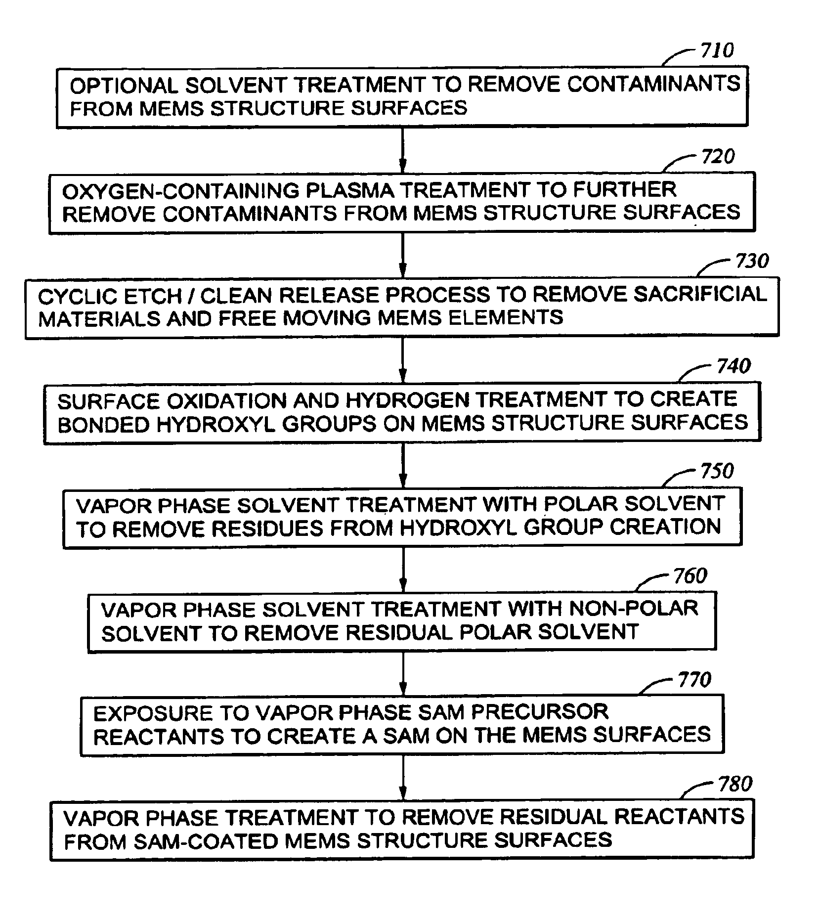
[0036]Disclosed herein is an integrated process for release and passivation of MEMS structures which includes formation of a SAM on MEMS surfaces. Exemplary processing conditions for performing various embodiments of the method of the invention are set forth below. In addition, various kinds of processing apparatus which may be used to carry out the method are described along with efficiencies which may be achieved by the use of particular processing apparatus.

[0037]As a preface to the detailed description, it should be noted that, as used in this specification and the appended claims, the singular forms “a”, “an”, and “the” include plural referents, unless the context clearly dictates otherwise.

[0038]I. Apparatus for Practicing the Invention

[0039]FIG. 3 shows across-sectional schematic of a single chamber plasma processing system of the kind which was used to carry out the experimentation described herein, in order to minimize initial equipment costs. A single chamber processing sy...


PUM

PropertyMeasurementUnit
volume %aaaaaaaaaa
volume %aaaaaaaaaa
pressureaaaaaaaaaa

Abstract

Disclosed herein is a method of improving the adhesion of a hydrophobic self-assembled monolayer (SAM) coating to a surface of a MEMS structure, for the purpose of preventing stiction. The method comprises treating surfaces of the MEMS structure with a plasma generated from a source gas comprising oxygen and, optionally, hydrogen. The treatment oxidizes the surfaces, which are then reacted with hydrogen to form bonded OH groups on the surfaces. The hydrogen source may be present as part of the plasma source gas, so that the bonded OH groups are created during treatment of the surfaces with the plasma. Also disclosed herein is an integrated method for release and passivation of MEMS structures which may be adjusted to be carried out in a either a single chamber processing system or a multi-chamber processing system.

Description

STATEMENT OF RELATED APPLICATION[0001]This application is a continuation-in-part of Ser. No. 10 / 300,970 filed Nov. 20, 2002 now U.S. Pat. No. 6,830,950 which is a CIP of U.S. patent application Ser. No. 09 / 850,923, filed May 7, 2001 now U.S. Pat. No. 6,576,489.FIELD OF THE INVENTION[0002]In general, the present invention is an integrated method for release and passivation of MEMS (micro-electro-mechanical systems) structures. In addition, a method of improving the adhesion of a hydrophobic self-assembled monolayer (SAM) coating to a surface of a MEMS structure is described, where the SAM is used to prevent stiction. The invention also pertains to the use a single chamber processing system to carry out the integrated release and passivation method, or to the use of a multi-chamber processing system which provides greater processing efficiencies.BRIEF DESCRIPTION OF THE BACKGROUND ART[0003]Micromachining technology compatible with semiconductor processes is used to produce a number of...

Claims


Application Information

Patent Timeline
Patent Type & Authority Patents(United States)
IPC IPC(8): B81B3/00B81C1/00
CPCB81B3/0005B81C1/0096B82Y30/00B81C2201/112B81C2201/0176
Inventor CHINN, JEFFREY D.GUENTHER, ROLF A.RATTNER, MICHAEL B.COOPER, JAMES A.LEUNG, TOI YUE BECKYBJORKMAN, CLAES H.
Owner APPLIED MATERIALS INC
Why Eureka
Try Eureka