[0002] Building a sustainable society requires a reduction in the dependency on fossil fuels and a lowering of the amount of
pollution generated.
Wastewater treatment is an area in which these two goals can be addressed simultaneously. As a result there has been a recent paradigm shift from disposing of waste to using it. Many bioprocesses can provide
bioenergy while simultaneously achieving the objective of pollution control. Industrial wastewaters from food-
processing industries and breweries, and agricultural wastewaters from animal confinements are ideal candidates for bioprocessing, because they contain high levels of easily degradable organic material. The vast quantity of organics results in a net
positive energy or economic balance even when heating of the liquid is required. In addition, they have a
high water content, which circumvents the necessity to add water. Such wastewaters are potential commodities from which
bioenergy may be produced.
Recovery of energy may reduce the cost of
wastewater treatment, and reduce our dependence on fossil fuels. Examples of bioprocessing strategies that can be used to treat industrial and agricultural
wastewater with generation of bioenergy are: methanogenic
anaerobic digestion to produce
methane, hydrogen
fermentation to produce hydrogen, and microbial
fuel cells (“MFC's”) to produce bioelectricity. Methanogenic
anaerobic digestion, hydrogen fermentation, and bioelectricity production share one property: the microbial
community in the reactors is mixed and selection of the
community is based on function. This is useful for the non-sterile, ever-changing, complex environment of wastewater treatment. In addition, the products from these bioprocesses can be easily separated as gases or bioelectricity.
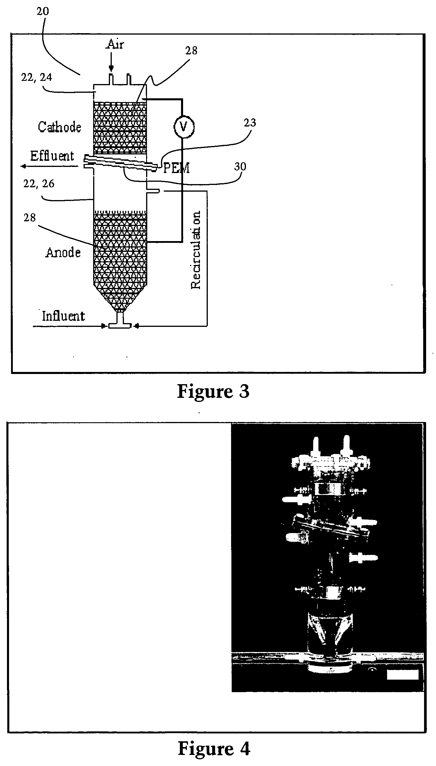
[0006] In order to solve these and other problems in the prior art, the inventors have developed a novel continuously-fed MFC that is particularly adapted to large scale use and is thus more practical for wastewater treatment: the upflow
microbial fuel cell (UMFC). The UMFC was developed with the goal of combining the advantages of the upflow
anaerobic sludge blanket (UASB)
system, which is the most popular anaerobic
bioreactor worldwide, with a dual-chamber MFC. The UASB
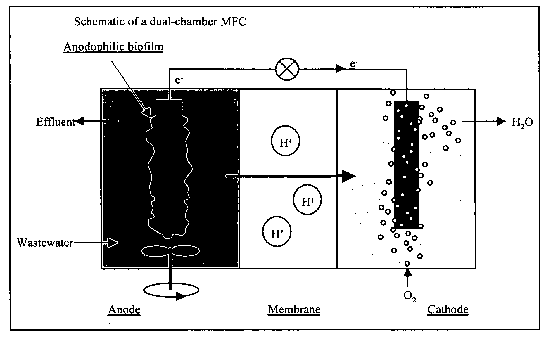
system and its derivatives are advantageous, because they eliminate the need for mechanical mixers by creating an upflow hydraulic flow pattern in the reactor. Unlike the conventional dual-chamber MFC configuration (as shown in FIG. 1), the present invention locates the anode and cathode chambers on top of each other and separate them with a
proton exchange membrane (Membrane International, Inc.; http: / / www.membranesinternational.com). In addition, commercially available carbon-
fiber foam with a surface area of 0.5 cm2 / cm3 (
ERG Materials and
Aerospace Corporation; http: / / www.ergaerospace.com) is used in the reactor to increase the anode
electrode surface. As a result, the anode chamber in the UMFC is operated as an
anaerobic filter, with a
biofilm on the carbon-
fiber foam, and an upflow hydraulic pattern to promote mixing without use of a mechanical mixer.
Wastewater influent is continuously fed at the bottom of anode chamber while
effluent is discharged from the top of same chamber, thereby establishing a continuous fluid flow through the UMFC. Microorganisms in the anode chamber degrade organic pollutants, produce protons and transfer electrons via an
external circuit. Protons pass through the
proton exchange membrane into a cathode chamber, where
oxygen takes electrons and protons to produce water. In this manner, electricity is continuously produced in greater
power density than previously possible with the prior art designs.
[0009] As an example of such further development, the inventors herein disclose a modified UMFC design wherein a generally cylindrical and U-shaped cathode chamber is positioned inside the anode chamber. Furthermore, granular articulated carbon can be used as the
electrode material. Testing by the inventors has indicated that such a design can greatly improve the UMFC's
power output.

