Touch panel

a touch panel and wiring technology, applied in the direction of user-computer interaction input/output, instruments, computing, etc., can solve the problems of insufficient weight and complicated wiring, and difficulty in giving a feeling of input manipulation to the manipulator, so as to reduce the weight and the size of the touch panel

Inactive Publication Date: 2007-06-05
SMK CORP
View PDF9 Cites 63 Cited by
  • Summary
  • Abstract
  • Description
  • Claims
  • Application Information

AI Technical Summary

Benefits of technology

[0032]In other words, according to this aspect of the invention, by providing a structure in which the pair of the electrodes of the piezoelectric substrate is connected to the conductive layer electrode of the movable plate or the...

Problems solved by technology

Hence, the pressing stroke of the movable plate is in an extremely small range from tens to hundreds microns, which makes it difficult to give a feeling of input manipulation to the manipulator.
When these wirings are withdrawn separately and connected to connectors, for example, when two piezoelectric substrates are provided on either end of the supporting substrate, three connectors are necessary in total; m...

Method used


Image

  • Touch panel
  • Touch panel
  • Touch panel

Examples


Embodiment Construction

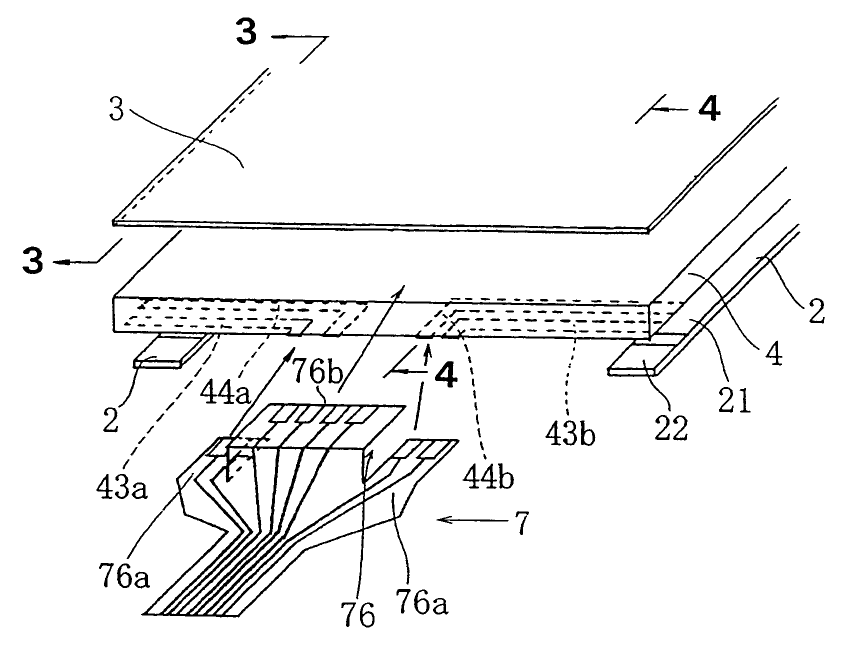
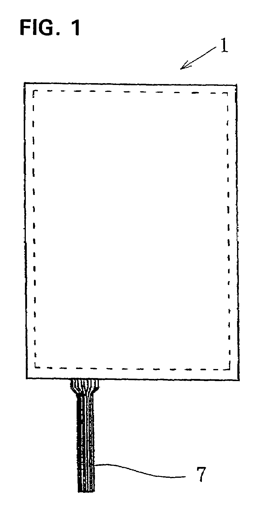
[0046]FIG. 1 is a view showing an outward appearance of a touch panel 1 of the invention. Wiring is provided by leading a single connector tail 7 from the touch panel 1.

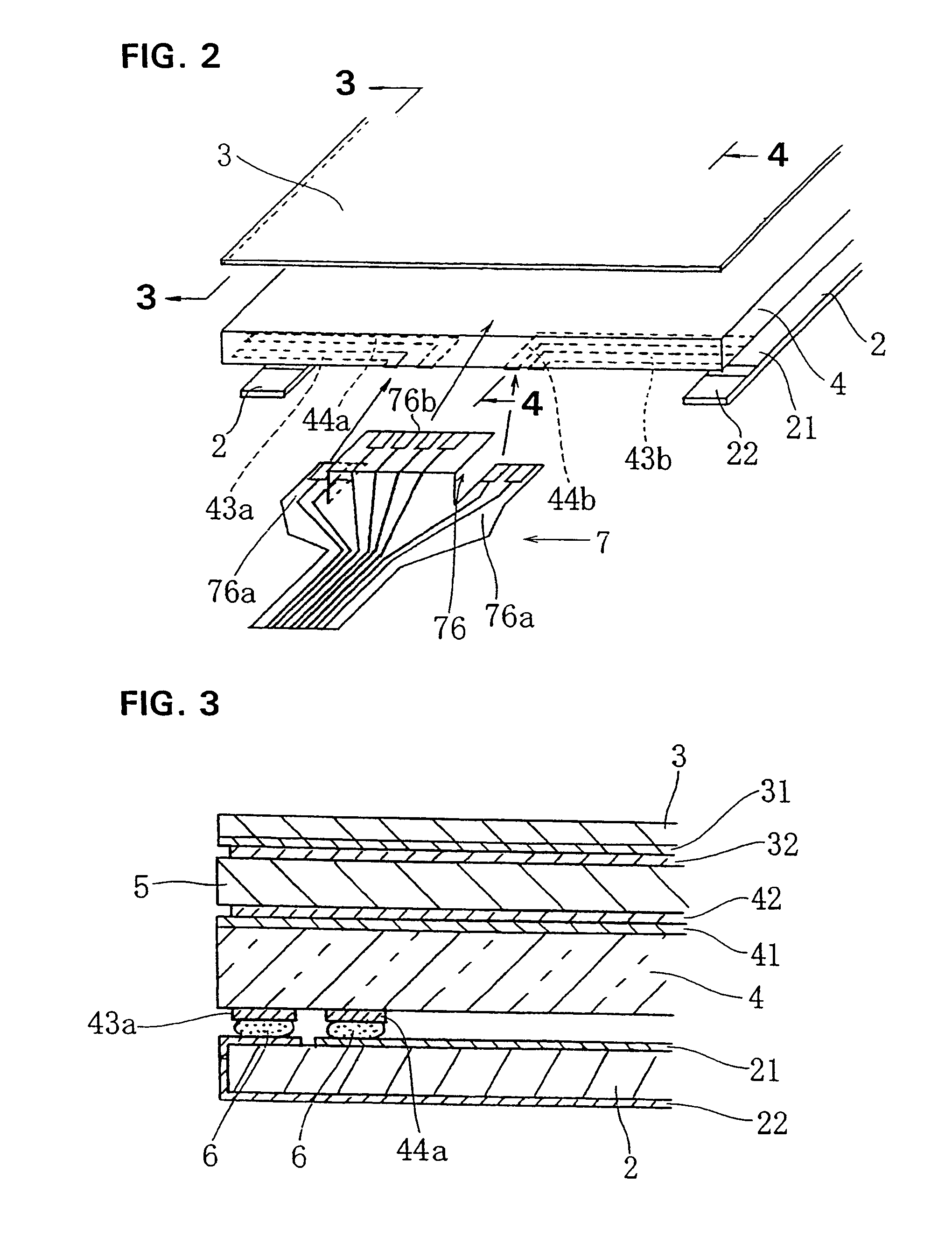
[0047]FIG. 2 is a view showing a wiring structure of a connector tail portion. FIG. 3 is a cross section, taken along the line 3—3 of FIG. 2, showing details of the wiring structure. FIG. 4 is a cross section, taken along the line 4—4 of FIG. 2, showing details of the wiring structure.

[0048]A movable plate 3 is a molded flexible rectangular sheet made of transparent synthetic resin, and PET (polyethylene terephthalate) is used herein.

[0049]The movable plate 3 can be made of an arbitrary material as long as it can slightly bend toward a supporting substrate 4 described below. It should be noted, however, that in the case of making a visible display portion (not shown) formed inside the supporting substrate 4 like in this embodiment, the supporting substrate 4 is made of a transparent material. Alternatively, in a case...


PUM


Abstract

A touch panel of the present invention in which a piezoelectric substrate is fixed to a movable plate or a supporting substrate has a reduced weight, size, and thickness by providing simpler wiring. The touch panel comprises: a movable plate having an input manipulation surface; a supporting substrate, disposed with a slight insulation gap from the movable plate, for supporting the movable plate from a back surface thereof; conductive layers on the movable plate and the supporting substrate on their respective opposing surfaces; and a piezoelectric substrate fixed to the movable plate or the supporting substrate. A pair of driving electrodes on the piezoelectric substrate are fixed to respective opposing surfaces of the piezoelectric substrate. A conductive layer electrode of the movable plate, a conductive layer electrode of the supporting substrate, and the pair of driving electrodes of the piezoelectric substrate are withdrawn integrally using a single connector tail.

Description

BACKGROUND OF THE INVENTION[0001]1. Field of the Invention[0002]The present invention relates to a wiring structure of a touch panel used in a touch-panel input device that gives a feeling of input manipulation to a manipulator who presses a movable plate, since the movable plate being pressed or a supporting substrate supporting the movable plate is allowed to vibrate. In particular, the present invention relates to a wiring structure of a touch panel that allows the movable plate or the supporting substrate to vibrate using a piezoelectric substrate.[0003]2. Description of the Related Art[0004]A touch panel is used in a touch-panel input device. The touch-panel input device is a device in which a movable plate and a supporting substrate are deposited with a slight insulation gap between conductive layers formed on their respective opposing surfaces. When the movable plate is pressed, the touch-panel input device electrically detects that the opposing conductive layers come in cont...

Claims


Application Information

Patent Timeline
IPC IPC(8): G09G5/00G06F3/041G06F3/03
CPCG06F3/041G06F3/04164G06F3/045G06F3/03
Inventor NAKAYAMA, NAOMIEGAMI, TAKEHIROIMAI, KAZUOYAGO, TAKESHI
Owner SMK CORP
Why Eureka
Try Eureka