Fiber optic sensing device and method of making and operating the same

a fiber optic and sensing device technology, applied in the field of chemical sensing, can solve the problems of limited operation temperature range, limited range of conventional optical and electrochemical sensing devices, and limited use of these sensors

Active Publication Date: 2007-06-05
FIBERGUIDE LTD
View PDF10 Cites 36 Cited by
  • Summary
  • Abstract
  • Description
  • Claims
  • Application Information

AI Technical Summary

Benefits of technology

[0015]In accordance with another embodiment, a chemical sensing probe comprises: (a) a chemical sensing device comprising a fiber core and a fiber cladding, wherein the fiber core comprises an index-modulated grating region having an apodized profile configured for increasing shedding of light into the fiber cladding, and wherein the fiber cladding is configured for reflecting at least some of the shed light back towards the fiber core; and (b) an optical reference sensing device configured for obtaining a reference signal representative of reflection of the light from or a transmission of light through the reference sensing device.

Problems solved by technology

Most of these sensors are limited by the operational conditions in which the sensors are employed.
For example, conventional optical and electrochemical sensing devices are often limited to relatively mild pH conditions and, as such, limited operational temperature ranges.
More specifically, conventional devices are typically limited to a pH range from about 5 to about 11 and temperatures lower than about 100° C.
However, it is difficult to use these fiber optic sensors as real-time monitoring sensing devices because the fluctuation of the light source and environmental sensitive fluorescent dye luminescence limit measurement accuracy.
It is difficult to identify different chemicals in an environment like a water exchanger, a pipeline, oil and gas storage tanks, or an industrial processing system.
Discrete optical, electrochemical and fiber optic sensors may not be scalable to meet a desired spatial resolution that is beneficial for accurate mapping of system conditions.
It is difficult to simultaneously detect multiple parameters, such as pH, salinity, corrosion, and temperature, through a single mechanically or chemically modified Bragg grating sensing device.
Such separation of sensed parameters is difficult and time-consuming.
Additionally, it is particularly challenging to fabricate multiple sensors on a single fiber cable when chemical etching a fiber with an inscribed Bragg grating structure.
In principle, these fiber optic sensors have potential distribution capability, but, as a practical matter, it is not an easy task to handle multiple delicate sensors.
In addition, the weak mechanical strength due to the thinner fiber grating cladding thickness can create failure modes.
Despite the removal of the cladding etch requirement, it is difficult to distribute many LPGs in a common chemical sensing system due to cladding modes crossover.
Typically, within a bandwidth of one hundred nanometers, for example, the number of the LPG sensors is limited because of the multiple transmission peaks from each LPG.
More practical difficulty lies in the detection of the chemical while other environmental factors such as temperature are varying.
The different temperature and chemical sensitivities of the transmission peaks make it difficult to distinguish the chemical signal from the environmental influence.
Although cladding modes numbers or crossover can be reduced for LPG sensors by chemical etching for a LPG-based sensing device, the same mechanical processing challenge occurs as that associated with mechanically modifying short-period FBGs.

Method used


Image

  • Fiber optic sensing device and method of making and operating the same
  • Fiber optic sensing device and method of making and operating the same
  • Fiber optic sensing device and method of making and operating the same

Examples


example 1

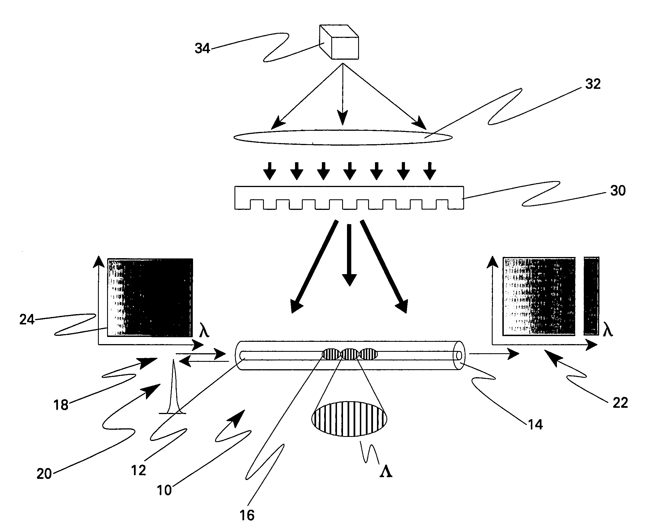
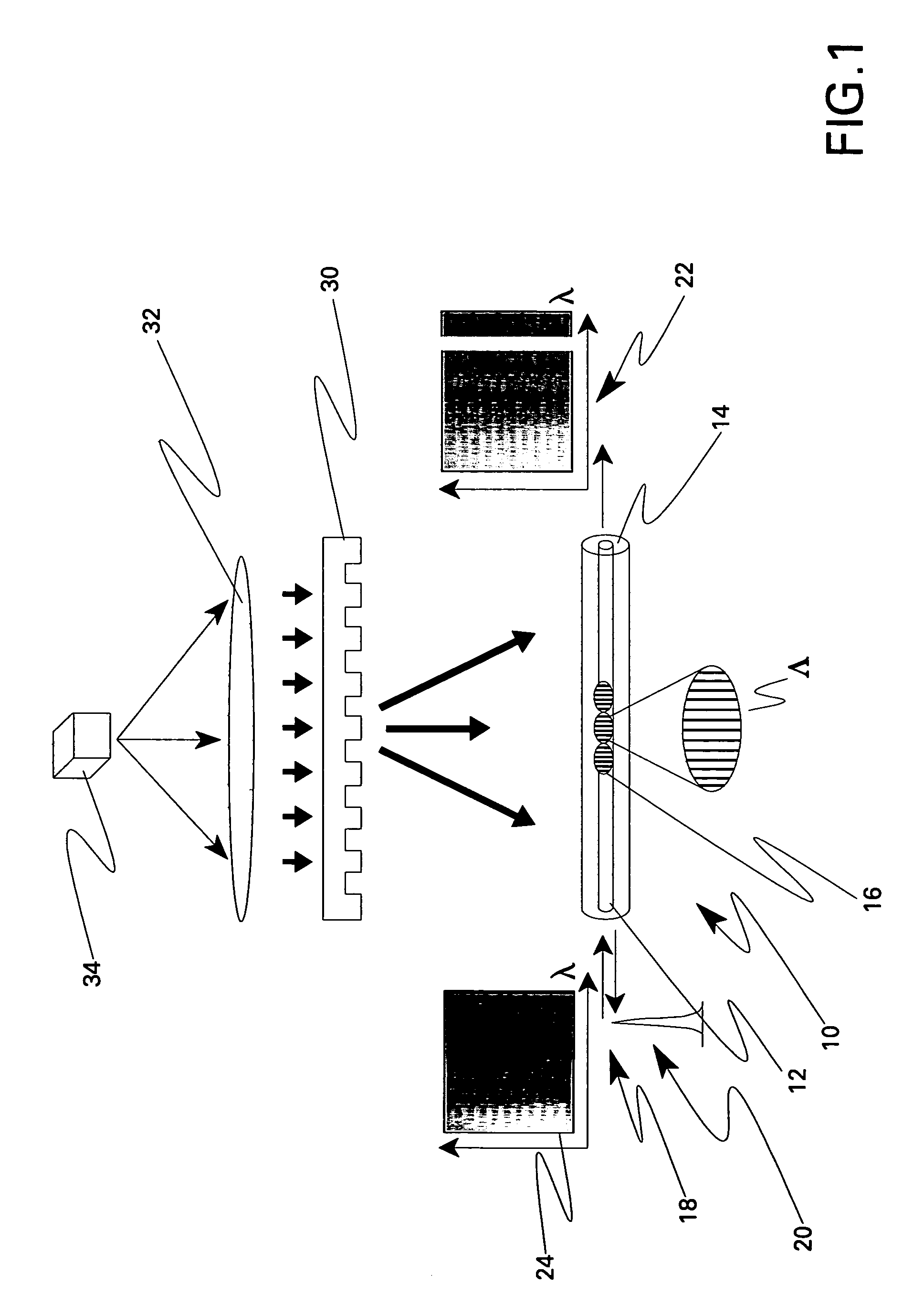
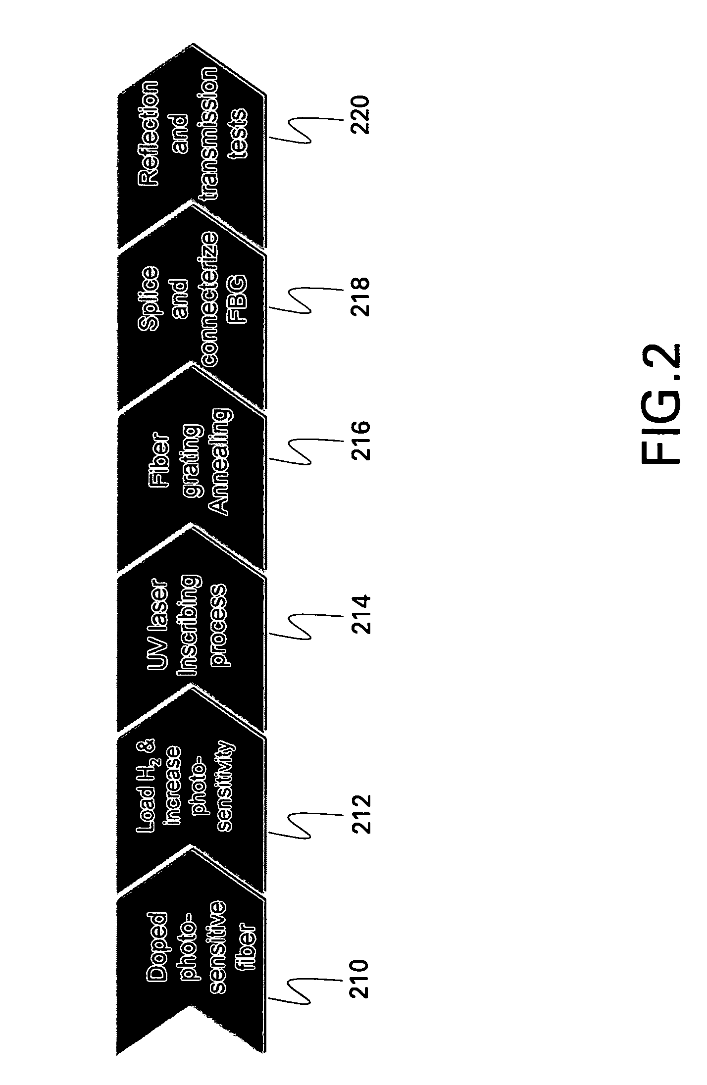
[0031]In one fabrication method example, a modulated FBG based chemical sensing device has been fabricated with a strong 244 nanometer wavelength ultraviolet (UV) light 34 inscription by a lens 32 and periodic modulated phase mask 34. Before the grating inscription, a hydrogen loading process was used to enhance the fiber core 12 photosensitivity. Fiber core 12 was a single mode core with a diameter of about nine micrometers and co-doped by about five percent to about seven percent mole GeO2 and about 10 ppm to about 100 ppm Fluorine. The combination of fiber cladding 14 and fiber core 12 was about 125 micrometers in diameter and without any doping elements. The refractive index modulation profile was apodized with a raised cosine pattern along the fiber axis.

[0032]A multiple apodization process can be used when the length of grating region 16 is larger than about 5 millimeter (mm). For example, several sequential apodization profiles are typically applied for a 36 mm length of fibe...

example 2

[0034]The sensing device described with respect to EXAMPLE 1 was illuminated by a near infrared broadband light source from a tunable laser diode, and the chemicals were detected by observing a time-dependent wavelength shift from an interrogation system in monitoring both reflectance and transmittance. The absorption processes of the target chemical modulate the fiber grating optical properties and thereby modulate the coupling properties between the cladding modes and fundamental mode. Chemical sensing based on this apodized FBG has experimentally shown perceivable Bragg resonant wavelength shift with 20–200 pm downshift and decay-like response characteristics from acetone, methanol, toluene, isopropyl alcohol, and hydrofluoric acid.

[0035]In a more specific method embodiment, the light comprises a test light and, prior to transmitting the test light, a training light is transmitted through grating region 16, a chemical (meaning at least one) is introduced into an environment of fi...

example 3

[0050]For verification, a sensing system was fabricated and included chemical sensing device 500, a polyimide recoated fiber Bragg grating as a real-time temperature sensing device 600, and a four channel interrogation system 718. A one-milliwatt tunable diode laser 714 was connected to the sensing fiber through a fiber optic coupler 712. The scanned wavelength, with a rate of 80 nanometers per second, was calibrated with a gas cell and sweep meter 716. The system resolution was 0.4 pm for chemical sensing device 500 sensing. A tracking algorithm in processor 720 for transmission-dip and reflected peak was used to record the time-dependent chemical sensing. Care was taken to maintain the gratings with a proper tensile stress during the measurements by maintaining the sensing probe 710 with a stable support structure or package 518 (FIG. 6).

[0051]As part of chemical sensing probe 710, two fiber Bragg gratings were inscripted on a germanium oxide doped photosensitive silica single-mod...


PUM


Abstract

A chemical sensing device comprises a fiber core and a fiber cladding. The fiber core comprises an index-modulated grating region having an apodized profile configured for increasing shedding of light into the fiber cladding, and the fiber cladding of the chemical sensing device is configured for reflecting at least some of the deflected light back towards the fiber core. The sensing device is applicable in methods and systems for sensing chemicals.

Description

BACKGROUND[0001]The invention relates generally to chemical sensing and more particularly to fiber grating-based chemical sensing devices, systems and methods.[0002]Fiber optic sensing methods have advantages including flexibility, small size, negligible weight, passivity, and immunity to electromagnetic interference. These characteristics make fiber optic sensors ideally suited for monitoring dynamic chemical and physical processes that are associated with changes in environment. The cascading capability of fiber optic sensing enables a distributed sensing application for large-area infrastructure embodiments such as oil tanks, pipelines, and power grid utilities in which fiber optic chemical sensing devices are embedded in multiple locations, some of which may be otherwise inaccessible.[0003]Various sensing devices have been used. For example, some chemical sensing embodiments depend on dye molecules that absorb a particular wavelength of light and re-emit the light a short time l...

Claims


Application Information

Patent Timeline
Patent Type & Authority Patents(United States)
IPC IPC(8): G02B6/00G01J1/04H01L21/00
CPCG01N21/7703G02B6/02085G01N21/774G01N21/39G01N2021/7706
Inventor XIA, HUAGUIDA, RENATODENG, KUNG LI
Owner FIBERGUIDE LTD
Why Eureka
Try Eureka