Rapid steel frame assembly

a steel frame and assembly technology, applied in the direction of girders, joists, foundation engineering, etc., can solve the problems of inability to adjust the height of the column attachment, the column attachment is not provided with height adjustment, and the c-shaped columns cannot be easily slipped, so as to achieve quick, easy and accurate positioning of the building columns

Inactive Publication Date: 2007-06-12
RIZZOTTO JOHN L
View PDF45 Cites 16 Cited by
  • Summary
  • Abstract
  • Description
  • Claims
  • Application Information

AI Technical Summary

Benefits of technology

[0034]It is an object of the present invention to use precisely located foundation assemblies to quickly, easily and accurately locate the building columns in both the horizontal and vertical planes.

Problems solved by technology

However, this attachment does not allow for height adjustment.
The columns are C-shaped and cannot be easily slipped over a foundation assembly.
However, there is no provision for height adjustment at the column attachment.
There is no provision to allow the trusses to be conveniently broken in two for transport and there is no provision to allow the columns to slip over the foundation members.
The position of the bolts is usually determined by a steel tape measure, which usually results in location errors in the order of ¼ to ½ inch.
These errors require the framing members to be cut and fitted on the site, a slow and costly process.
The reason for these errors are many and include the use of a tape measure, the use of aggregate in the concrete which makes it difficult to precisely set a bolt in place and the fact that the bolt is let stand while the concrete sets up.
However, at this time, with the column suspended in the air, it is difficult to correct for the horizontal plane location errors of the bolts, while at the same time connect the column to the bolts and erect the column in a perfectly vertical position.
This prior art assembly procedure does not lend itself to precisely locating the column and results in building members not fitting together and requiring time consuming and costly redrilling and cutting on the job site to complete the assembly of the building.

Method used


Image

  • Rapid steel frame assembly
  • Rapid steel frame assembly
  • Rapid steel frame assembly

Examples


Embodiment Construction

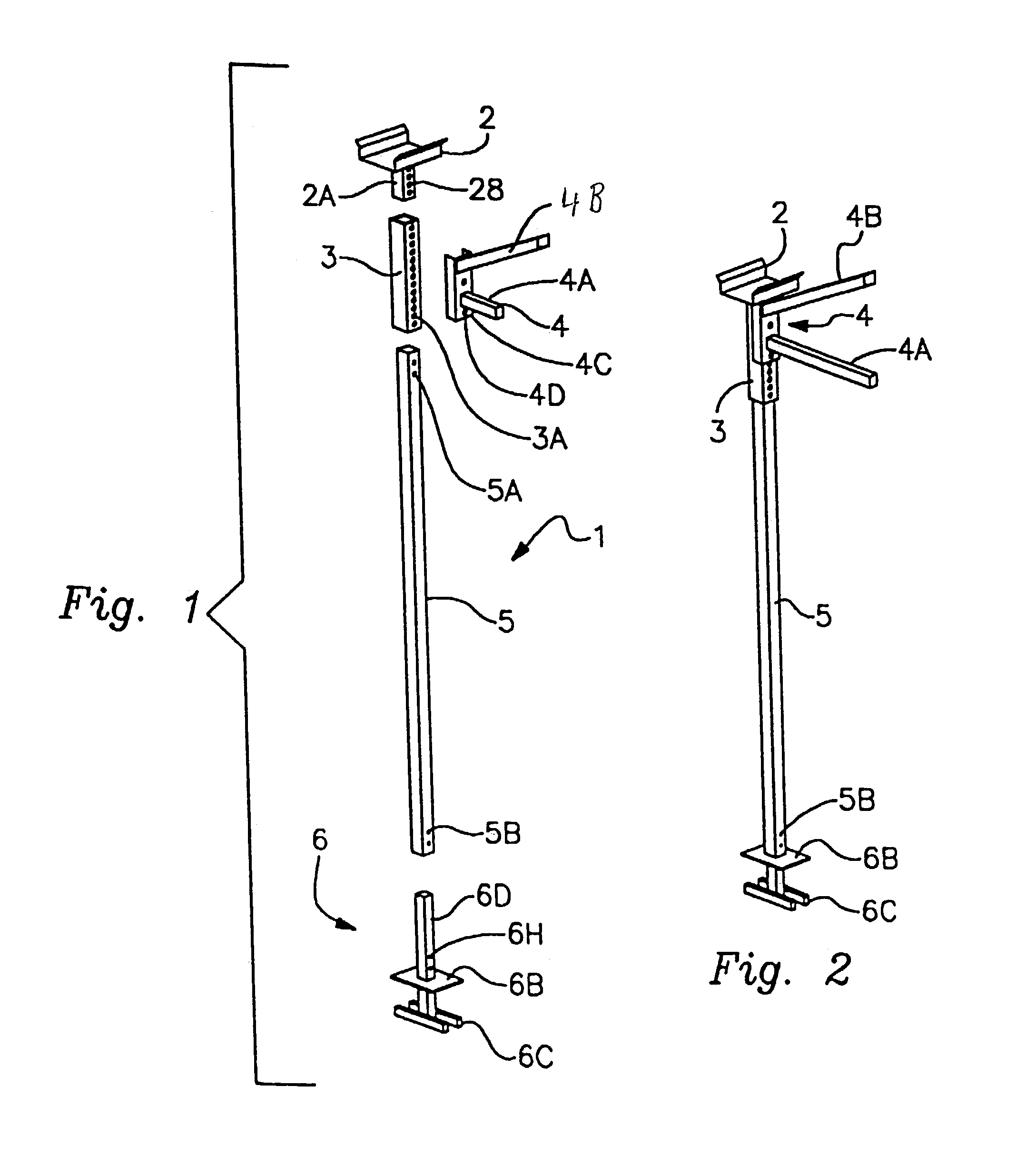
[0062]FIG. 1 is an exploded view showing a main column 5 used in the assembly of a steel building along with a gutter 2, a truss assembly 4 and a foundation assembly 6. Only a portion of the truss is shown in this Figure. This portion is made up of a left truss connection plate 4C, a lower chord 4A, a top member of the truss 4B, and an attachment plate 4C. At the top of this drawing is an adjustable rain gutter 2 with a support arm 2A, which contains a series of evenly spaced holes 2B. Directly beneath the support arm 2A, is a structural adjustment sleeve 3 which includes a line of vertically positioned evenly spaced holes 3A.

[0063]Directly beneath the structural adjustment sleeve 3 is the column 5, which contains holes at its top5A and holes at its bottom 5B. Directly beneath the column 5 is the foundation assembly 6, which includes a low column 6D, a series of vertical holes 6A in the low column 6D, a horizontal plate 6B which is attached approximately midway up from the bottom of...


PUM


Abstract

A framing assembly system for steel building that substantially reduces assembly time while maintaining excellent strength and mechanical integrity and has vastly improved resistance to uplift forces. Foundation assemblies or anchor structures are first precisely located before concrete is poured to form the foundation, encasing the anchor structures within the foundation. Columns may then be attached to the anchor structures without the need for readjusting the location of the columns. The rest of the building framework is subsequently attached to the columns. The resulting structure is highly resistant to uplift forces and seismic effects while being much faster and simpler to assemble than previous structures. Cracking of the concrete foundation prior to the complete curing of the concrete is also reduced.

Description

[0001]This application is a continuation-in-part of U.S. patent application Ser. No. 10 / 095,764, filed on Mar. 13, 2002 now U.S. Pat. No. 6,679,023, which claims priority to U.S. Provisional Application Nos. 60 / 315,172, filed on Aug. 28, 2001, and 60 / 276,623, filed on Mar. 19, 2001, herein incorporated by reference.FIELD OF THE INVENTION[0002]The present invention relates to steel frame buildings and more particularly to such buildings that are designed to facilitate the precise location of the column which results in rapid, low cost building assembly without the need for cutting, redrilling or welding of any of the structural members. The present invention also relates to steel frame buildings that are greatly resistant to uplift forces and seismic effects, and a method of constructing the same.BACKGROUND[0003]There are a number of prior art steel buildings containing features designed to facilitate the assembly of these buildings as evidence by the patents reference below.[0004]U....

Claims


Application Information

Patent Timeline
Patent Type & Authority Patents(United States)
IPC IPC(8): E02D27/42E02D27/32E02D27/00E04BE04B1/24E04B1/343E04C3/04E04C3/11E04C3/40E04C5/06E04H12/22
CPCE02D27/42E02D27/50E04B1/24E04B1/34352E04C3/11E04C3/40E04C5/06E04H12/2261E04B1/2403E04B2001/2421E04B2001/2439E04B2001/2451E04B2001/2463E04B2001/249E04C2003/0491Y10S52/11
Inventor RIZZOTTO, JOHN L.
Owner RIZZOTTO JOHN L
Why Eureka
Try Eureka