Foldable pedal assembly

a pedal assembly and bicycle technology, applied in the field of bicycle pedals, can solve the problems of adverse effect of foot of user and bicycle pedal conta

Inactive Publication Date: 2007-06-12
CHEN CHUNG I
View PDF7 Cites 31 Cited by
  • Summary
  • Abstract
  • Description
  • Claims
  • Application Information

AI Technical Summary

Problems solved by technology

The conventional foldable bicycle pedal 10 is disadvantageous in that: coupling of the pedal body 11 and the crank-connecting member 15 through the interaction action between...

Method used


Image

  • Foldable pedal assembly
  • Foldable pedal assembly
  • Foldable pedal assembly

Examples


Embodiment Construction

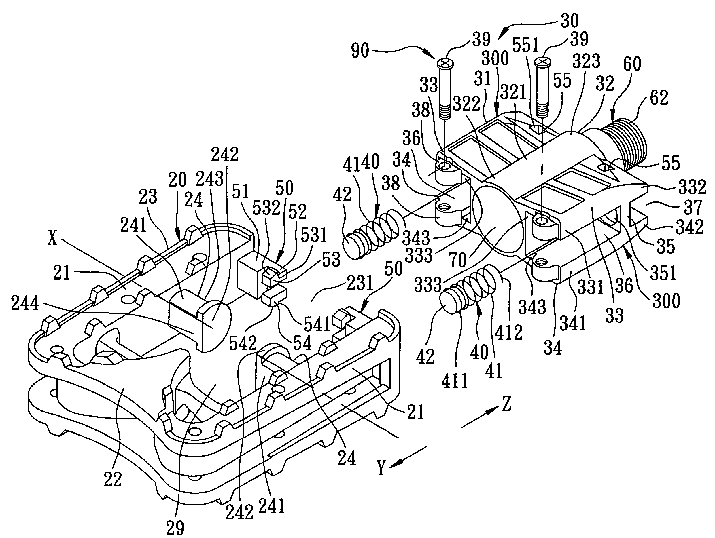
[0021]Referring to FIGS. 3 and 6, the preferred embodiment of a foldable pedal assembly according to the present invention is shown to be adapted to be mounted on one end portion of a bicycle crank 80 of a bicycle. The foldable pedal assembly includes: a pedal frame 20 defining a frame space 29 and formed with left and right studs 24 that are opposite to each other in an axial direction relative to an axis (X) and that protrude into the frame space 29; a crank-connecting part 30 adapted to be connected to the bicycle crank 80 and including left and right wing units 300 that define left and right recesses 36, respectively, the crank-connecting part 30 extending into the frame space 29, the left and right studs 24 extending into the left and right recesses 36 and being pivoted to the left and right wing units 33, 34, respectively, so as to permit rotation of the pedal frame 20 about the axis (X) relative to the crank-connecting part 30; left and right urging members 40 disposed in the...


PUM


Abstract

A foldable pedal assembly includes: a pedal frame formed with left and right studs opposite to each other in an axial direction; a crank-connecting part including left and right wing units that define left and right recesses, respectively, the left and right studs extending into the left and right recesses and being pivoted to the left and right wing units, respectively; left and right urging members disposed in the left and right recesses to urge the pedal frame in a first direction transverse to the axial direction, and to urge the crank-connecting part in a second direction opposite to the first direction; a first limiting unit abutting against at least one of the left and right studs by urging action of the urging members; and a second limiting unit abutting against at least one of the left and right wing units by urging action of the urging members.

Description

BACKGROUND OF THE INVENTION[0001]1. Field of the Invention[0002]The invention relates to a bicycle pedal, more particularly to a foldable pedal assembly for a bicycle.[0003]2. Description of the Related Art[0004]Many consumers favor foldable bicycles due to convenience when carrying the same. To further reduce the size after folding, pedals mounted on a foldable bicycle are also foldable in design. As shown in FIGS. 1 and 2, a conventional foldable bicycle pedal 10 includes: a pedal body 11 having an intermediate rod 112, a pair of spaced apart lateral rods 111 which extend from opposite ends of the intermediate rod 112 and which are formed with slide grooves 114, and a pair of upper and lower ribs 113 interconnecting the lateral rods 111, one of the ribs 113 being formed with an engaging hole 115; a movable member 12 that is slidably received in the slide grooves 114, that is formed with a through-hole 123, and that has a stud 121 and a pair of protrusions 122 disposed opposite to ...

Claims


Application Information

Patent Timeline
IPC IPC(8): B62M3/00G05G1/30
CPCB62K15/006B62M3/08B62K2015/003Y10T74/2168Y10T74/2172
Inventor CHEN, CHUNG-I
Owner CHEN CHUNG I
Why Eureka
Try Eureka