Vibratory screening machine and vibratory screen and screen tensioning structure

a vibratory screening machine and vibratory screen technology, applied in the direction of screening, solid separation, chemistry apparatus and processes, etc., can solve the problems of distorting channels formed on the side edges of the screen, having certain deficiencies, and having to move the tensioning channel. , to achieve the effect of rapid mounting and demounting of the vibratory screening screen

Inactive Publication Date: 2007-06-12
DERRICK CORP
View PDF46 Cites 100 Cited by
  • Summary
  • Abstract
  • Description
  • Claims
  • Application Information

AI Technical Summary

Benefits of technology

[0005]It is accordingly one object of the present invention to provide an improved tensioning system for a vibratory screening machine which permits rapid mounting and demounting of vibratory screening screens.
[0007]Yet another object of the present invention is to provide an improved mounting arrangement on a vibratory screen which does not require conventional channel-types of mounting structures.
[0008]A further object of the present invention is to provide an improved vibratory screening screen in which there is no excessive wear in the areas which are adjacent the side edges of the screening screen.
[0009]Yet another object of the present invention is to provide an improved vibratory screening machine wherein the tensioning structure which is mounted on the sides of the machine engages the screen from underneath, thereby obviating the requirement for holes in the sides of the machine above the screens through which material to be screened can flow. Other objects and attendant advantages of the present invention will readily be perceived hereafter.

Problems solved by technology

However, this system had certain deficiencies.
One deficiency was that the channels formed on the side edges of the screen would distort.
Another deficiency was that the tensioning channels had to be moved clear of the channels on the edges of the screens before the screens could be demounted from the machine.
This was a time-consuming operation, considering that generally twelve bolts had to be loosened on each side of the machine before screens could be removed and thereafter all twenty-four bolts had to be tightened after new screens had been replaced.
In addition, the use of the foregoing channel-type of tensioning structure was especially detrimental when used in conjunction with undulating screening screens because the material to be screened would accumulate in the areas of the channels and thus create turbulent flow of the material to be screened which caused excessive wear on the undulations adjacent the side edges of the screens.

Method used


Image

  • Vibratory screening machine and vibratory screen and screen tensioning structure
  • Vibratory screening machine and vibratory screen and screen tensioning structure
  • Vibratory screening machine and vibratory screen and screen tensioning structure

Examples


Embodiment Construction

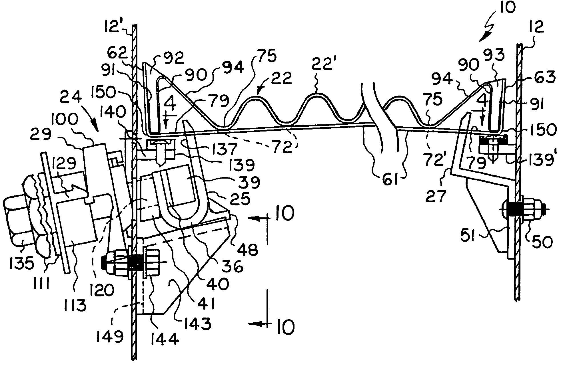
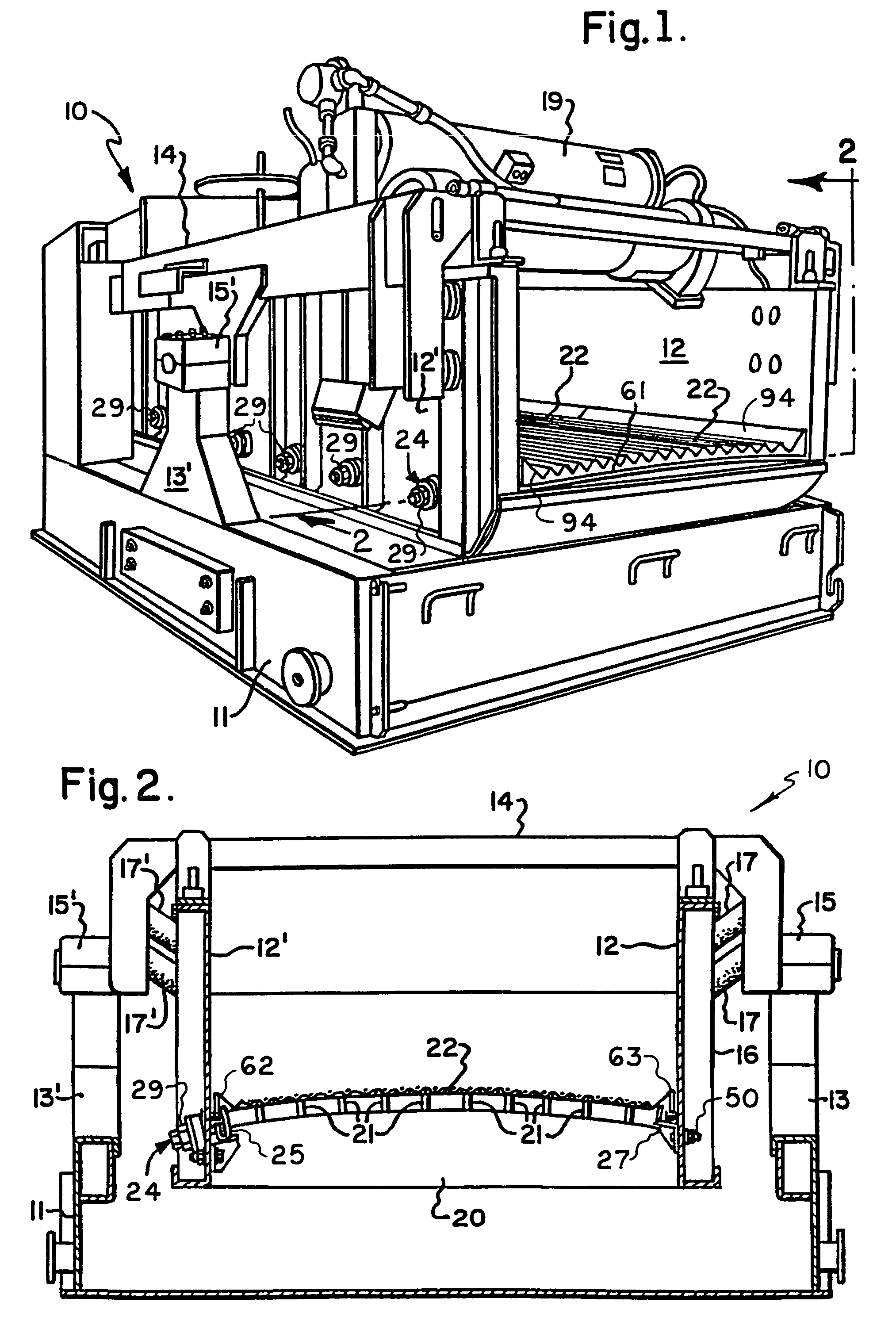
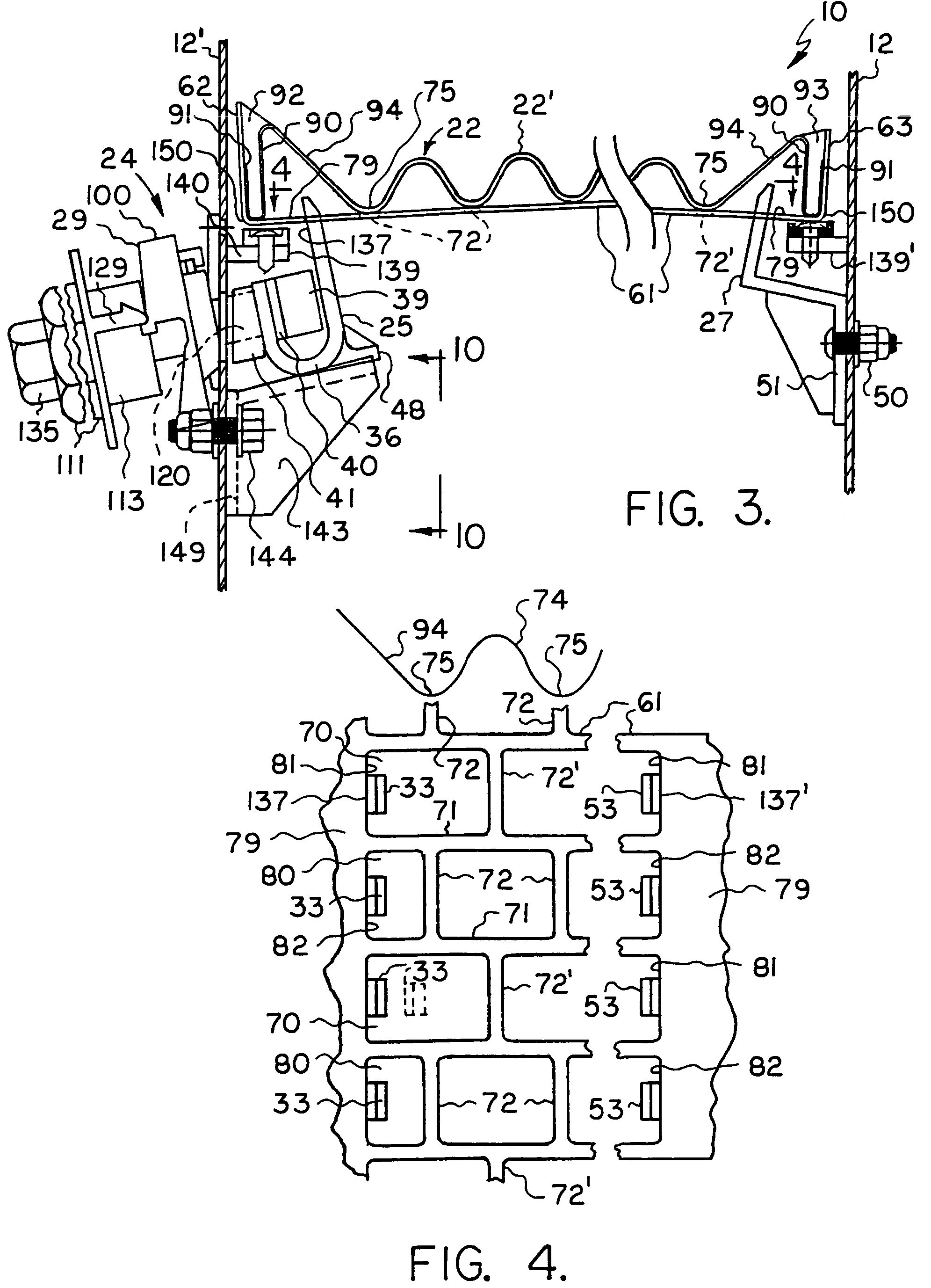
[0034]The improved screen tensioning structure of the present invention is for mounting on a vibratory screening machine of any suitable type. Vibratory screening machine 10 of FIGS. 1-3 is of conventional construction except for certain structure, namely, the structure associated with the improved tensioning structure of the present invention. Thus, the vibratory screening machine 10 may be of the types shown in U.S. Pat. Nos. 5,332,101 and 4,882,054, the latter two patents being incorporated herein by reference and which should be referred to for a better understanding of the present invention. By way of specific description, the vibratory screening machine 10 includes a base 11 having a vibratory frame 14 suitably mounted thereon. Standards 13 and 13′, which are mirror image counterparts, are mounted on base 11, and they pivotally support frame 14 by means of trunnions 15 and 15′. Side walls 12 and 12′ are resiliently mounted on frame 14 by means of elastomeric connectors 17 and ...


PUM


Abstract

A vibratory screening machine having opposite sides with a plurality of stationary aligned tensioning members mounted on one side and a plurality of nut actuated movable tensioning members mounted on the opposite side and a vibratory screening screen mounted on the stationary and movable tensioning members. The tensioning members have upstanding fingers which are received in apertures in the plates of the vibratory screen, and the edge portions of the vibratory screen include screening material which extends all of the way to the extreme edges of the supporting plate and the fingers are below the screening material. Also, the tensioning structure is mounted on the side walls of the vibratory screening machine below the vibratory screen.

Description

CROSS-REFERENCE TO RELATED APPLICATIONS[0001]Not ApplicableSTATEMENT REGARDING FEDERALLY SPONSORED RESEARCH OR DEVELOPMENT[0002]Not ApplicableBACKGROUND OF THE INVENTION[0003]The present invention relates to an improved vibratory screening machine and an improved vibratory screen and to an improved tensioning structure for a vibratory screening machine.[0004]In the past, a conventional way of mounting vibratory screens on vibratory screening machines was by utilizing elongated channel members on the sides of the machines which interfitted with channels formed at the side edges of a screening screen. However, this system had certain deficiencies. One deficiency was that the channels formed on the side edges of the screen would distort. Another deficiency was that the tensioning channels had to be moved clear of the channels on the edges of the screens before the screens could be demounted from the machine. This was a time-consuming operation, considering that generally twelve bolts h...

Claims


Application Information

Patent Timeline
Patent Type & Authority Patents(United States)
IPC IPC(8): B07B1/49B07B1/48
CPCB07B1/48B07B1/485
Inventor MOONEY, JAMES A.WOJCIECHOWSKI, KEITH F.
Owner DERRICK CORP
Why Eureka
Try Eureka