Temperature compensated RF circuitry

a technology of rf circuitry and rf, which is applied in the direction of transmission, transmission monitoring, electrical equipment, etc., can solve the problems of excessive loss of the typical, inexpensive coaxial transmission line between the radio and the antenna at these frequencies, waste of power, and further expense and power wastage, so as to improve the mounting arrangement and permit reliable operation.

Inactive Publication Date: 2006-02-16
YOUNG MICHAEL F +3
View PDF2 Cites 9 Cited by
  • Summary
  • Abstract
  • Description
  • Claims
  • Application Information

AI Technical Summary

Benefits of technology

[0009] It is still further an object of the invention to provide for an improved mounting arrangement for the internal printed circuit boards directly to the housing cover to provide for minimum VSWR from the coaxial connectors to the PC board strip line traces.
[0010] It is still further an object of the invention to provide temperature compensated RF level sensing circuitry to permit reliable operation over a very wide temperature range.

Problems solved by technology

Further, since the radios are Spread Spectrum devices, they can generally tolerate interference from other radios transmitting in the same geographical area.
The problem here is that the losses in the typical, inexpensive coaxial transmission line between the radio and the antenna at these frequencies can be excessive unless prohibitively expensive cable is used.
Putting an antenna on a tall radio tower or building would give clear line of sight to many locations, but this is largely defeated by the transmission cable loss.
However, this is in general unsatisfactory due to the fact that not only are both transmit and receive amplifiers are on at all times, thus leading to wasteful power usage, but also heavy filtering is also necessary to keep the transmit and receive signals from interfering with each other, leading to further expense and power wastage.
Still further, since each transmit and receive signal must be put to a separate frequency to avoid interference, this design is wasteful of spectrum bandwidth, a scarce commodity in many applications.

Method used


Image

  • Temperature compensated RF circuitry
  • Temperature compensated RF circuitry
  • Temperature compensated RF circuitry

Examples


Embodiment Construction

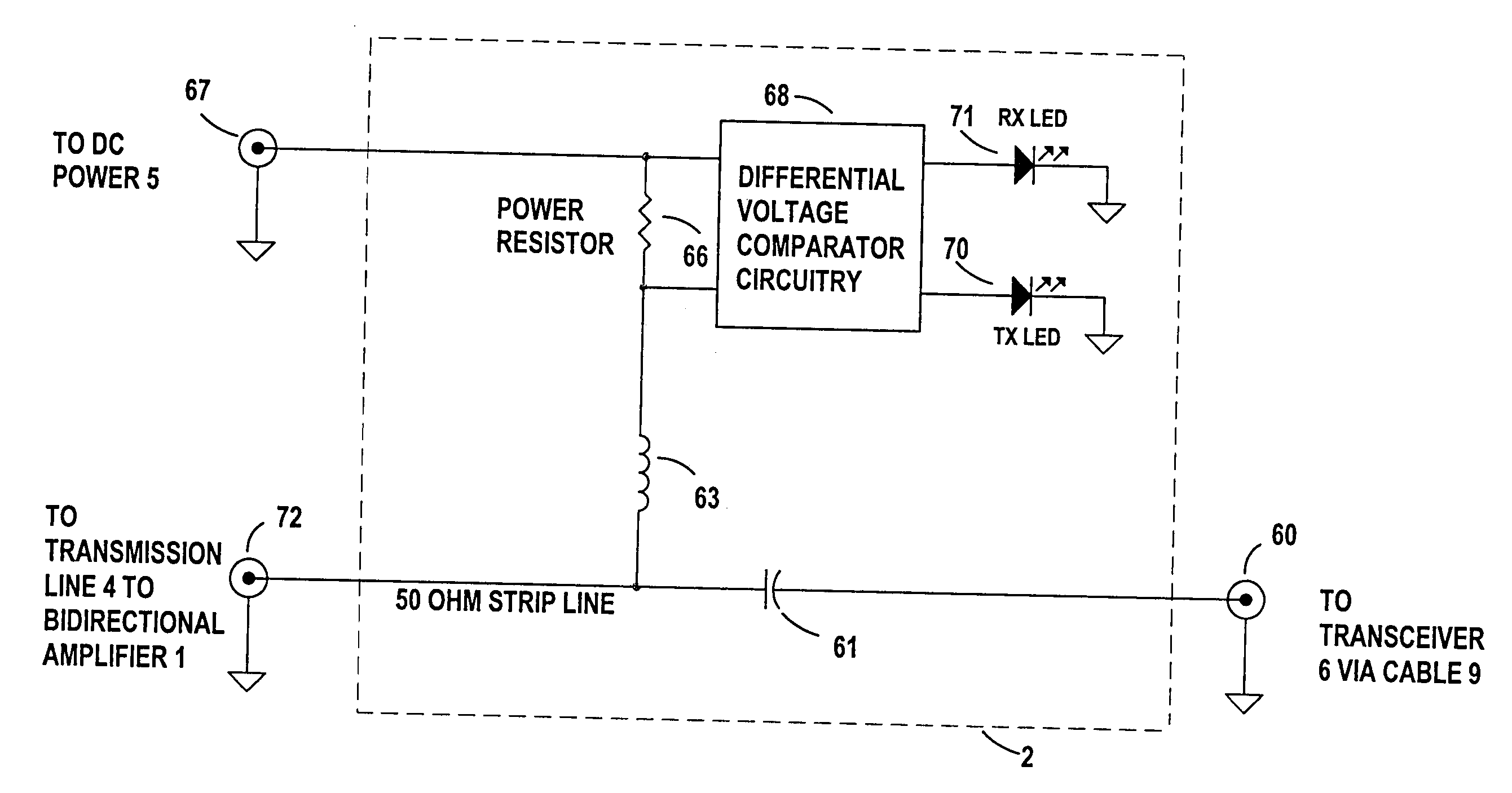
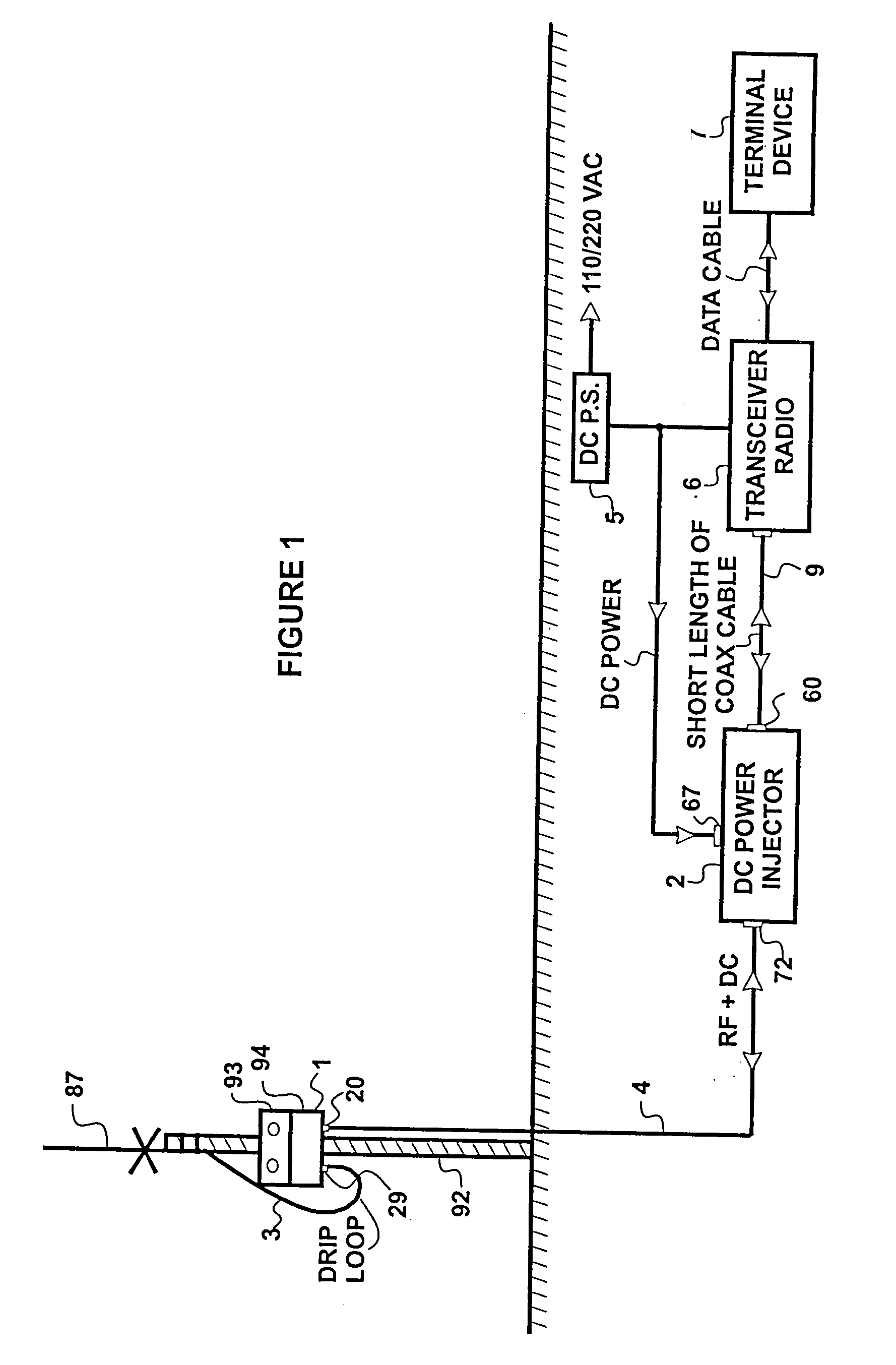
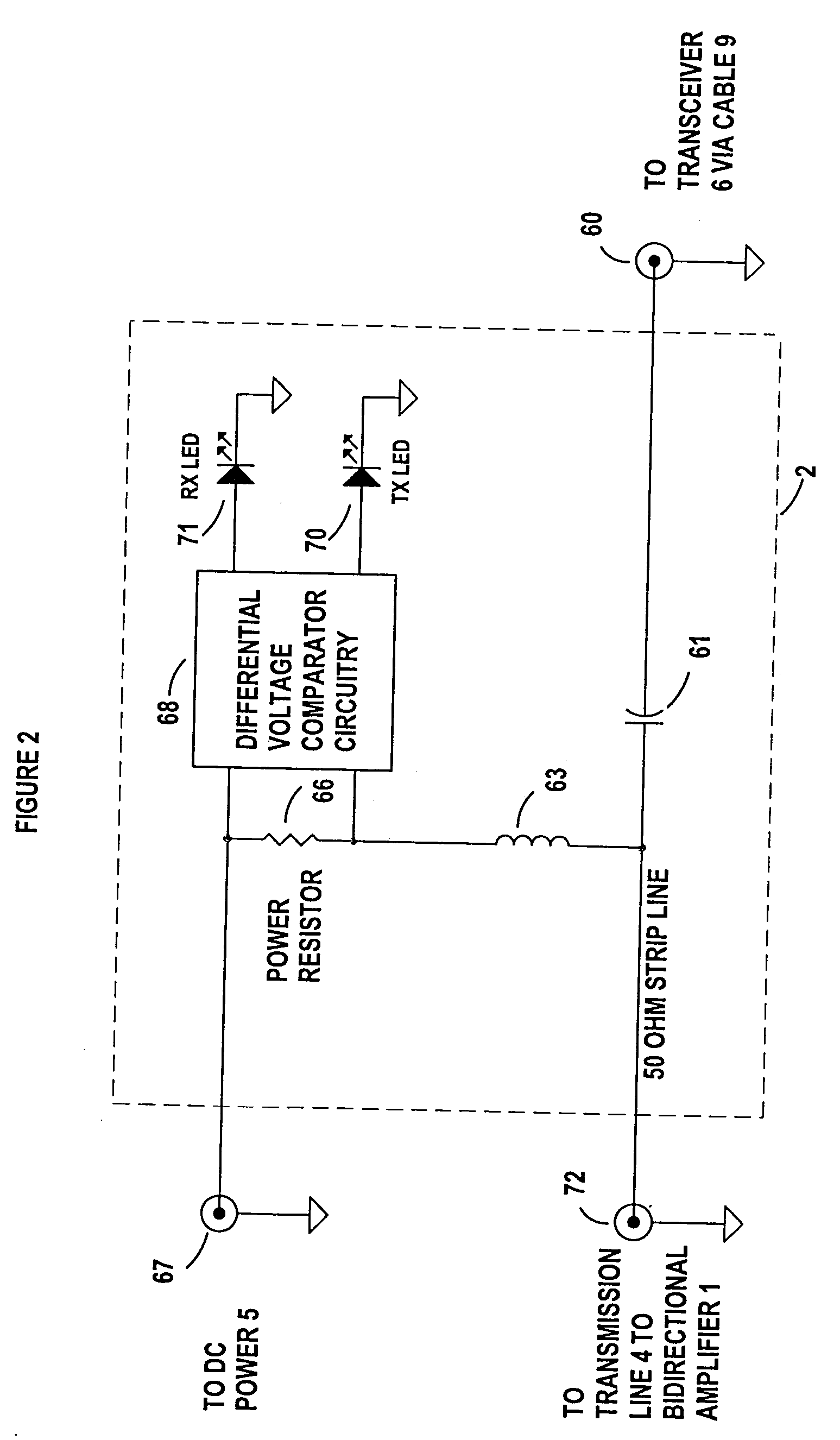
[0026]FIG. 1 show the remote bi-directional switching amplifier telecommunications system in a preferred typical installation. The bi-directional amplifier 1, inside the housing enclosure 94; the DC power input to the housing enclosure 94 from the DC power injector 2 supplied through connection 20, connection between the bi-directional switching amplifier I at 29 to the antenna 87 is made through a short length of inexpensive connecting cable 3 and the L-bracket 93 in conjunction with the mast 92 are the primary preferred components of the remote part of the system. The secondary components include a transmission line 4 connected to the housing enclosure 94 at 20, a DC Power Injector 2 preferably located remote from the bi-directional switching amplifier I housing 94, a DC Power Supply 5 which can be either DC or AC line operated, a radio transceiver 6, an appropriate computer, router or terminal device 7, and connecting cables between the various elements, such as 9 between the DC ...


PUM


Abstract

A temperature compensated RF sensing circuitry for use in a remotely mountable weatherproof bi-directional, half-duplex switching amplifier system designed to provide maximum range for low power half-duplex radios such as Spread Spectrum radio transceivers in utilizing a voltage reference that is connected between a power supply circuit and a reference potential with a thermistor for temperature compensation purposes.

Description

CLAIM OF PRIORITY AND CROSS REFERENCE TO RELATED APPLICATION [0001] This application is a divisional of and claims priority to and incorporates by reference, in its entirety, U.S. application Ser. No. 09 / 505,201, titled “Bi Directional Switched RF Amplifier, Waterproof Housing, Electrostatic Overvoltage Protection Device, and Mounting Bracket Therefor”, filed Feb. 16, 2000 and is a Conversion of Provisional Application Ser. No. 60 / 120,639, filed Feb. 18, 1999 BACKGROUND OF THE INVENTION [0002] The present invention is a result of the proliferation of low power, Spread Spectrum radio modem devices in the 902-928 MHz, 2.4 GHz and 5.7 GHz bands. Popularity of these radio devices is largely due to FCC regulations that allow appropriately certified radio transceivers to be operated license free. This certification requirement restricts the transmitter output power in order to enable many users to share the band. Further, since the radios are Spread Spectrum devices, they can generally to...

Claims


Application Information

Patent Timeline
Patent Type & Authority Applications(United States)
IPC IPC(8): H04B1/38H04B1/00H04B1/18H04B1/40H04B1/44H04B17/00
CPCH04B1/40H04B1/18
Inventor YOUNG, MICHAEL F.JONES, HUNTERCASAER, JOHNAKIMOV, PAUL
Owner YOUNG MICHAEL F
Why Eureka
Try Eureka