Lightweight annular interturbine duct

a technology of annular interturbine ducts and interturbines, which is applied in the direction of engine fuctions, motors, leakage prevention, etc., can solve the problems of high manufacturing cost, complex configuration, and bulky construction, and achieve the effect of reducing wall thickness

Active Publication Date: 2007-06-12
PRATT & WHITNEY CANADA CORP
View PDF21 Cites 61 Cited by
  • Summary
  • Abstract
  • Description
  • Claims
  • Application Information

AI Technical Summary

Benefits of technology

[0004]It is therefore an aim of the present invention to provide a new lightweight ITD having reduced wall thickness as compared to conventional cast interturbine ducts.

Problems solved by technology

Such a configuration is complex and bulky, however, not to mention expensive to manufacture.

Method used


Image

  • Lightweight annular interturbine duct
  • Lightweight annular interturbine duct
  • Lightweight annular interturbine duct

Examples


Embodiment Construction

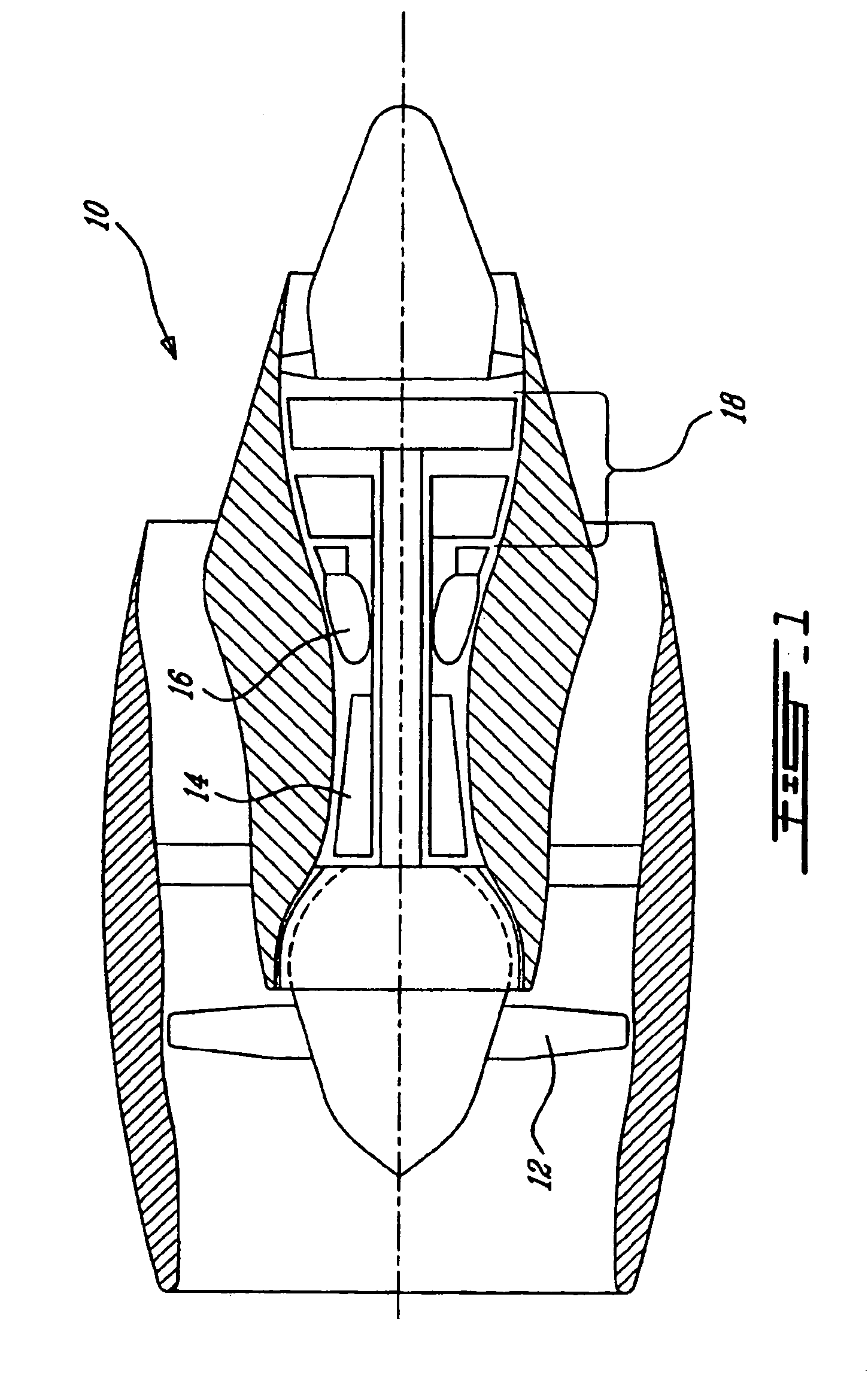
[0013]FIG. 1 illustrates a gas turbine engine 10 of a type preferably provided for use in subsonic flight, generally comprising in serial flow communication a fan 12 through which ambient air is propelled, a multistage compressor 14 for pressurizing the air, a combustor 16 in which the compressed air is mixed with fuel and ignited for generating an annular stream of hot combustion gases, and a turbine section 18 for extracting energy from the combustion gases.

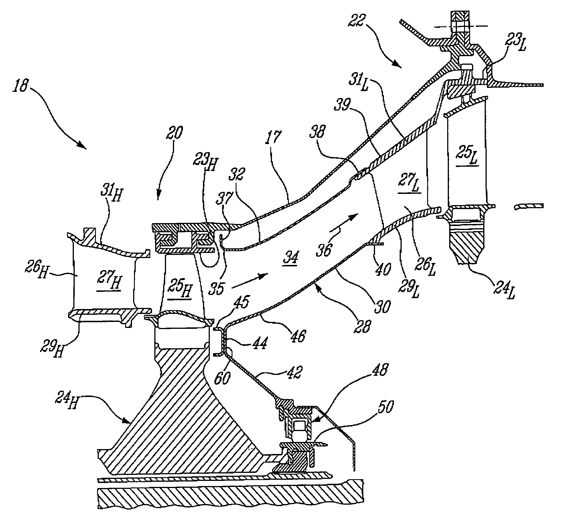
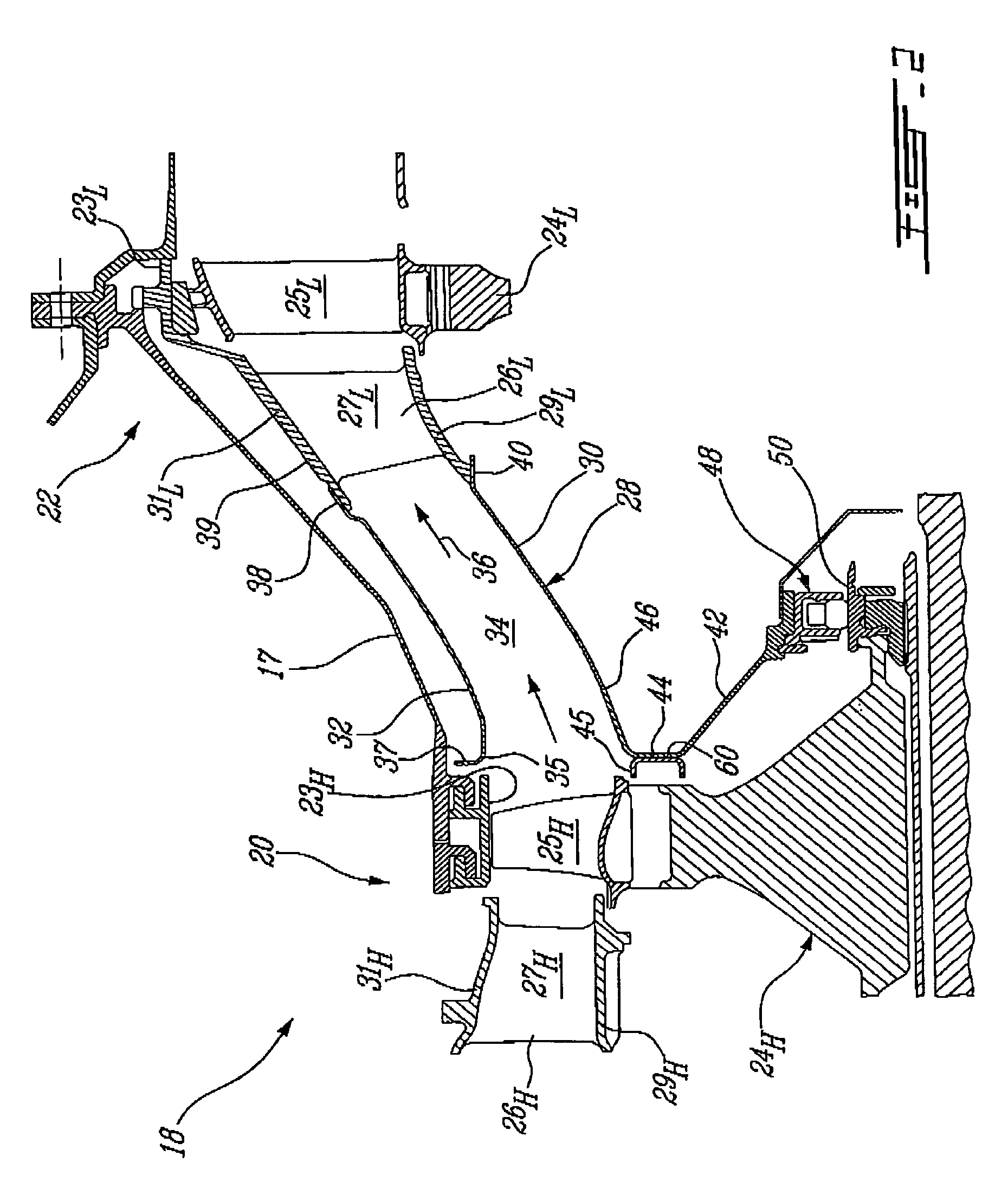
[0014]As shown in FIG. 2, the turbine section 18 comprises a turbine casing 17 containing at least first and second turbine stages 20 and 22, also referred to as high pressure turbine (HPT) and low pressure turbine (LPT) stages, respectively. Each turbine stage commonly comprises a shroud 23H, 23L, a turbine rotor 24H, 24L that rotates about a centerline axis of the engine 10, a plurality of turbine blades 25H, 25L extending from the rotor, and a stator vane ring 26H, 26L for directing the combustion gases to the rotor. The sta...


PUM


Abstract

An interturbine duct for channelling combustion gases between two axial turbine stages. The interturbine duct is made of sheet material to provide a relatively lightweight construction.

Description

TECHNICAL FIELD[0001]The invention relates generally to gas turbine engines and, more particularly, to an interturbine duct construction.BACKGROUND OF THE ART[0002]The interturbine duct (ITD), sometimes referred to as the interstage duct, channels hot combustion gases from an axial high pressure turbine (HPT) stage to an axial low pressure turbine (LPT) stage. In multi-spool turbofan engines, the ITD is an annular duct of significant length which is typically cast integrally as a part of the LPT vane set, and thus forms in essence an extension of the LPT vane, as shown in U.S. Pat. No. 5,485,717. As gas turbine engine size decreases, the casting size becomes an increasing proportion of the engine weight, since castings cannot scale down linearly as castings can only be made reliably down to a certain minimum thickness. U.S. Pat. No. 5,016,436 discloses a double-skinned sheet metal ITD arrangement, in which cooling air is circulated between the skins to cool the hot inner skin. The d...

Claims


Application Information

Patent Timeline
Patent Type & Authority Patents(United States)
IPC IPC(8): F01D25/24F01D25/28
CPCF01D9/02F01D9/06F05D2220/321F05D2230/237F05D2260/20
Inventor DUROCHER, ERICPIETROBON, JOHN WALTER
Owner PRATT & WHITNEY CANADA CORP
Why Eureka
Try Eureka