Method for determining an axle geometry and sensor for its execution

a technology of a sensor and an axle geometry, applied in the direction of instruments, measurement devices, surveying and navigation, etc., can solve the problems of lines, circles, or ellipses, affecting the evaluation of images, and conventional measurement methods for analyzing the axle geometry of a wheel on a motor vehicle, so as to increase the overall recording reliability

Inactive Publication Date: 2007-06-12
SIEMENS AG
View PDF16 Cites 48 Cited by
  • Summary
  • Abstract
  • Description
  • Claims
  • Application Information

AI Technical Summary

Benefits of technology

[0010]An object of the present invention is to provide a method and a sensor for measuring an axle geometry of a wheel on a motor vehicle. Another related object is to increase the overall recording reliability in the data processing to achieve a robust embodiment of the corresponding sensor.SUMMARY OF THE INVENTION
[0017]Consistent with the present invention, it is proposed that the measurement of the axle geometry, or the determination of a normal vector of a wheel, is accomplished preferably via a full-surface projection of light, along with a coding of the light that is also spread over the surface, onto the face of the wheel. The light reflected from the face of the wheel is then recorded as a full-surface image by an image converter, from a direction other than that in which the light was projected. This method yields the direct and enormous advantage that, instead of only a few measurement points being available (as are available using conventional methods), several million measurement points are available for evaluation purposes. Therefore, the visible face of the axle-mounted wheel can be characterized by a picture upon which the evaluation of many pixels can be performed. As a result, a robust and stable image recording and processing system is provided in that every unevenness on the face of the wheel (particularly on the generally flat, ring-shaped, outer wheel cover) is recorded, and a reference plane can reliably be determined. Further, each bead occurring in the pneumatic tire in the vicinity of the contact area of the tire with the ground can be evaluated as unevenness or as interference.
[0019]In a particularly advantageous formulation of the present invention, for example, either striated patterns with varying periodicity, monochrome lattice structures, or color coding can be used as the coding. It is important that the coding is provided over an area so that the recording reliability for data or image processing is guaranteed at each point of the object to be recorded. Another form of the coding can be given, for example, by a two-dimensional color pattern consisting of colored pattern elements that provide a particularly compact and, therefore, interference-safe color pattern for the coding. This results in an advantage that the projection angle of a pattern element in the recorded image of the two-dimensional color pattern projected on an object can be determined reliably. A further advantage is the fact that such a color pattern need be projected on the object only once.
[0021]Consistent with the present invention, using a video method or a video camera results in advantages in as much as this constitutes a current, generally available and proven method for image recording, which keeps the system costs within limits.
[0023]A recorded distance image, also called a topographical image, is initially fully illuminated by the sensor, consistent with the present invention. This results in a full recording of the face of the wheel. Because the image evaluation in the image converter is based on the corresponding full-area image recorded, the image evaluation can be restricted to important object ranges relevant to image processing in an advantageous way by using an intermediate mask. For example, in this manner the centralized range that usually reproduces the rim of a wheel can be ignored. It is also conceivable for a number of sub-surface reference surfaces to be placed along the circular face area of the cover, and to be recorded and evaluated accordingly. For example, in this manner the bead of a pneumatic tire resulting from the vehicle's weight can be ignored when processing the image.
[0027]Consistent with the present invention, distance values taken from the topographical image can also be supplemented by detecting color variants. This enables the recording of specific colors on the tire, on the rim, or on similar elements visible on the face of the wheel.

Problems solved by technology

However, conventional measurement methods for analyzing an axle geometry of a wheel on a motor vehicle have a disadvantage in that they project only lines, circles, or ellipses, as geometrically structured light patterns, on a wheel to be measured.
In particular, the influence of unevenness on a tire cover surface of a motor vehicle tire plays an important role in that it interferes with the evaluation of the image, or it does not allow a stable recording of the measured values.
This is not possible with conventional methods in which either the tire is aligned by determining the position of the tire rim, or the tire cover is scanned or illuminated with only a few contour lines.

Method used


Image

  • Method for determining an axle geometry and sensor for its execution
  • Method for determining an axle geometry and sensor for its execution
  • Method for determining an axle geometry and sensor for its execution

Examples


Embodiment Construction

[0044]The present invention will now be described in detail by describing illustrative and non-limiting embodiments thereof with reference to the accompanying drawings. In the drawings, the same reference characters denote the same elements.

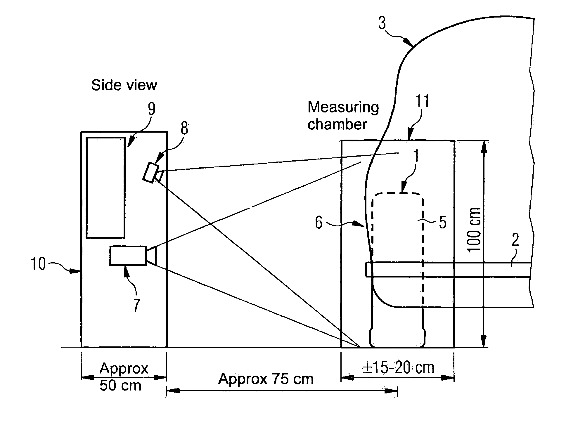
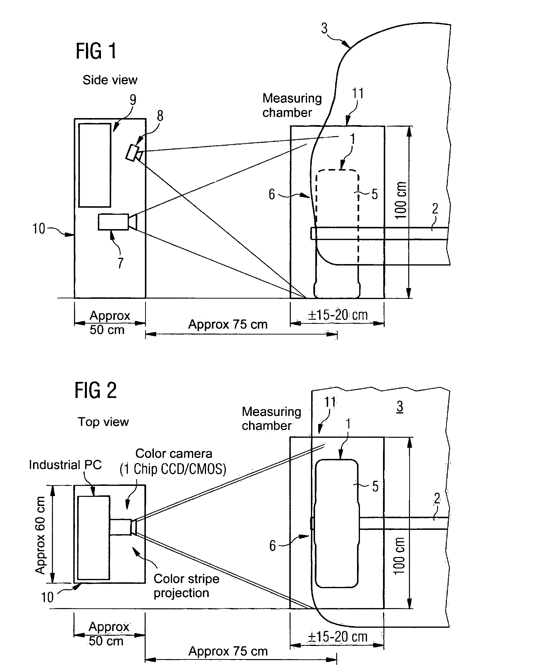
[0045]FIG. 7 is a diagrammatic representation of a wheel of a motor vehicle. The left portion of FIG. 7 shows the area of a wheel 1 that can be observed when facing the wheel. As shown in FIG. 8, moreover, a rim 4 is usually fitted to an axle 2. Further, a ring-shaped tire cover 5 is fitted to the rim 4. In particular, the laterally visible face of tire cover 5 is generally used for measuring an axle geometry.

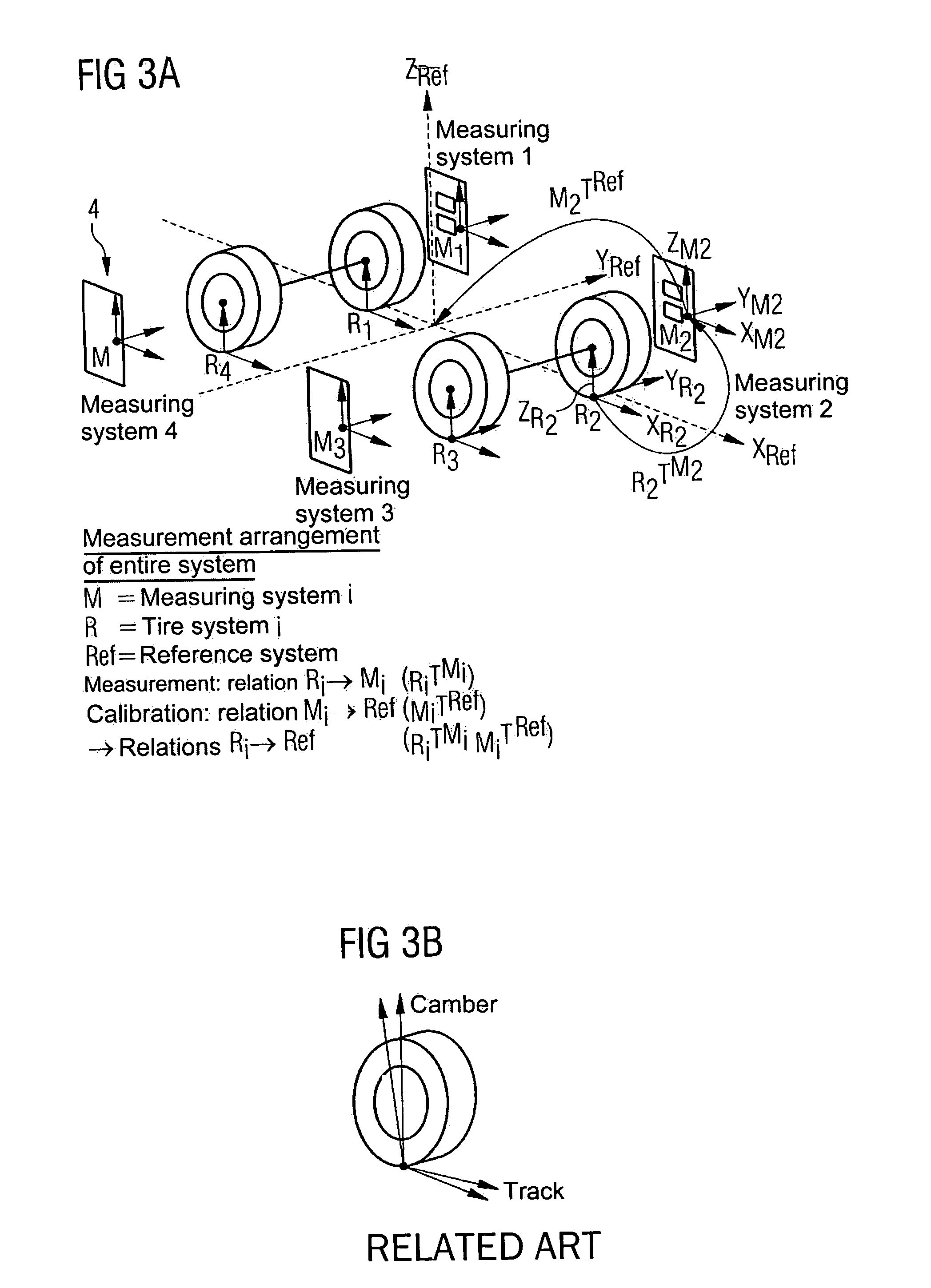
[0046]As shown in FIG. 8, laser probes are used in conventional methods of measuring axle geometry that apply contour lines 13, which are radially aligned on an area of the tire cover 5 of the wheel 1. For example, a laser probe that illuminates the top part of the wheel 1 can apply an illumination that can be used for determining the positi...


PUM


Abstract

Method for determining an axle geometry by recording and evaluating a topographical image of a face (6) of a wheel (1) fitted to an axle (2), and a sensor (10) for execution of the method. The method includes projecting light with a coding onto an area on the face (6) of the wheel (1) from a projecting direction; recording the light reflected from the area on the face (6) of the wheel (1) with an image converter (8), from a direction other than the light projecting direction; determining three-dimensional surface coordinates for the topographical image of the face (6) of the wheel (1) from the recorded light; and evaluating the topographical image in relation to a reference system.

Description

[0001]The present application is based on German Patent Application No. 10335829.3, filed on Aug. 5, 2003, which is incorporated into this application by reference in its entirety.FIELD OF AND BACKGROUND OF THE INVENTION[0002]The present invention relates to a method and a sensor for determining an axle geometry, such as the track and camber on an axle of a motor vehicle. In general, an axle geometry is determined for each wheel fitted to an axle by means of determining a normal vector on the face of the wheel in relation to a common reference system.[0003]An axle geometry on fitted wheels is usually measured during the final assembly of the motor vehicle or when working on the running gear of the vehicle in a workshop. In order to adjust the relative alignment of the wheels in relation to a reference system (e.g., the axle or the entire vehicle) by adhering to specific set point values, the actual, measured values must first be determined. With these actual values, the wheels are t...

Claims


Application Information

Patent Timeline
Patent Type & Authority Patents(United States)
IPC IPC(8): G01B11/26G01B11/25G01B11/275G01C1/00
CPCG01B11/2755G01B2210/14G01B2210/286
Inventor FORSTER, FRANKJAHN, LARSLALONI, CLAUDIO
Owner SIEMENS AG
Why Eureka
Try Eureka