
Side rail pad system for patient support apparatus

a technology for supporting devices and side rails, which is applied in the field of side rail systems, can solve the problems of inability to maintain a fixed association between cushions and patient support platforms, inability to accommodate the articulation of bed frames, and inability to maintain the stability of bed frames, so as to facilitate the movement of patients, improve the structural shape and design, and facilitate the effect of preventing movemen

Active Publication Date: 2007-06-19
HUNTLEIGH TECH LTD
View PDF2 Cites 6 Cited by
  • Summary
  • Abstract
  • Description
  • Claims
  • Application Information

AI Technical Summary

Benefits of technology

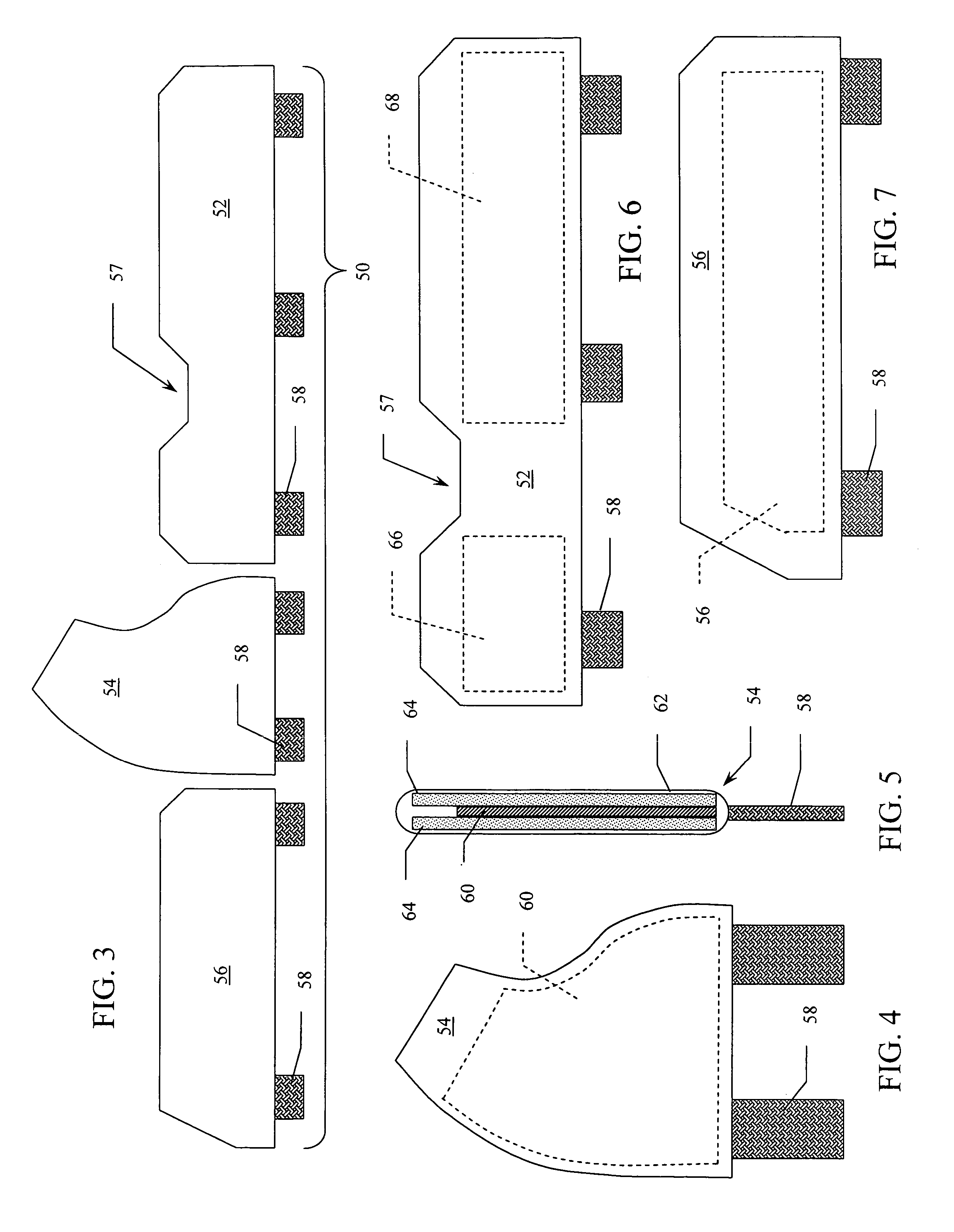
The present invention is a side rail pad system for use in patient support platforms that improves safety and comfort without sacrificing versatility and articulation movement. The system includes modifications to existing side rail designs and structures that provide appropriate closures or barriers for the safety and comfort of the patient. The side rail pad system includes flexible hinges that allow the pads to move between a placement that fills the space between the side rails and the mattress, and a placement away from the side of the mattress when the side rails are raised or lowered. The pad components are composed of layered, rigid or semi-rigid plate elements and foam pads, providing a firm but comfortable barrier to the patient's movement. The system allows for the continued articulation of the bed frame, despite the presence of the pad component.

Problems solved by technology

The various components of the basic patient support system that serve to enclose the patient within the platform area give rise to new problems associated with the safety and comfort of the patient.
Because it is necessary for these various enclosing panels to move and articulate themselves as the bed frame moves and articulates, there are necessarily gaps, openings, and passages between the various panel components, and between the panel components and the mattress itself.
Such systems clearly suffer from the inability to maintain a fixed association between the cushions and the patient support platform and to accommodate the articulation of the bed frame.
While efforts have been made in the past to improve safety and comfort for the patient, such efforts often fail to allow the continued versatility associated with existing articulating bed frames.

Method used


Image

  • Side rail pad system for patient support apparatus
  • Side rail pad system for patient support apparatus
  • Side rail pad system for patient support apparatus

Examples


Embodiment Construction

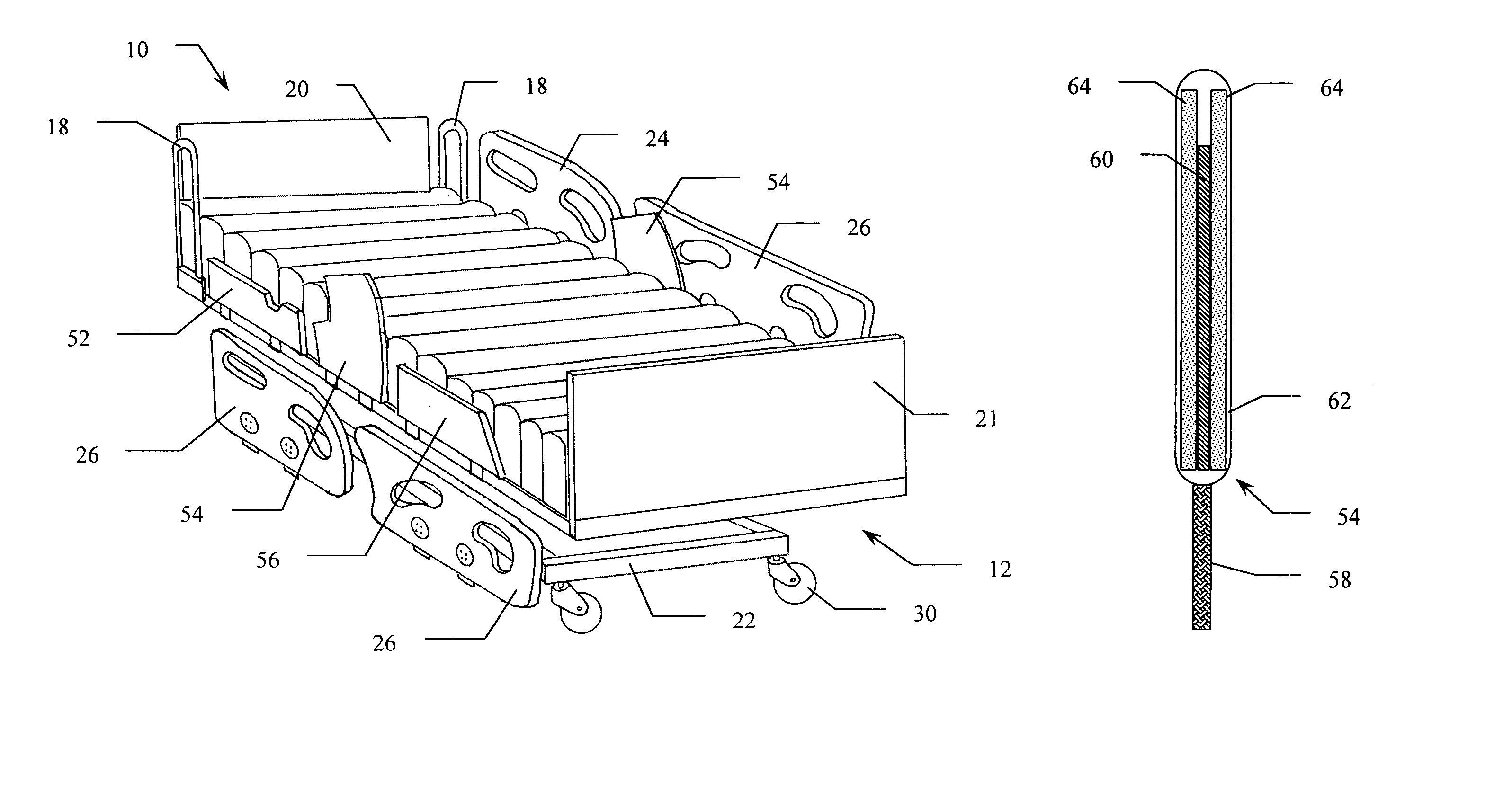
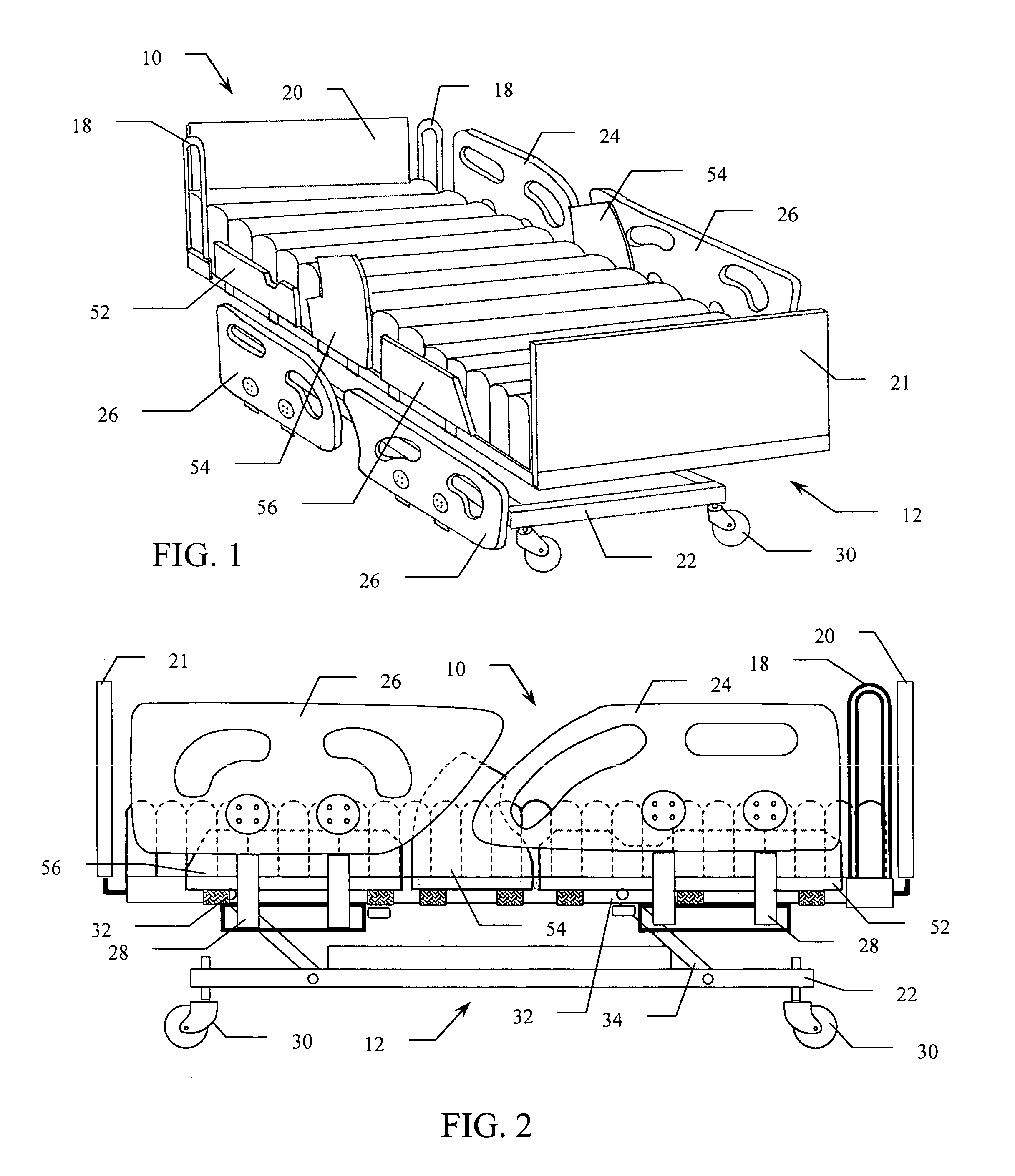
[0022]Reference is made first to FIG. 1 for a general description of a patient support system implementing the side rail pad system of the present invention. In FIG. 1, bed 10 is shown in a perspective view with one set of side rails elevated and a second set of side rails lowered as may typically be the case in a hospital setting. Bed 10 is comprised of frame 12 positioned on, and supported by base 22. Mattress 16 is positioned on top of frame 12 and may be any of a number of different mattress structures including air inflation mattress systems. Base 22 is made mobile by the provision of a plurality of casters 30 positioned thereon.

[0023]Enclosing the surface area of mattress 16, are head board 20 and foot board 21 at the upper and lower extremes of the mattress surface area. On the sides of mattress 16 are head space bars 18, upper side rails 24, and lower side rails 26. The upper and lower side rails 24 and 26 positioned on either side of mattress 16 are mirror images of each ot...


PUM


Abstract

A side rail pad system that provides modifications and components operable in association with hospital beds and the like that are designed to articulate. The system improves upon the structural shape of the side rails used in association with the articulating bed frames and provides an arrangement of side rail pads that are positioned between the side rails and the existing mattress platform. The side rail pads are positioned on the bed frame with flexible hinges in a manner that allows their alternate movement between a placement that fills the space between the side rails and the mattress when the side rails are in a raised position, and a placement away from the side of the mattress when the side rails are rotated into a lowered position.

Description

CROSS REFERENCE TO CORRESPONDING APPLICATIONS[0001]This application claims the benefit under Title 35 U.S. Code §119(e) of U.S. Provisional Application No. 60 / 542,385 filed Feb. 6, 2004.BACKGROUND OF THE INVENTION[0002]1. Field of the Invention[0003]The present invention relates to side rail systems utilized on patient support platforms and beds. The present invention relates more specifically to a system of partially rigid pads positioned in conjunction with the side rails of patient support platforms, hospital beds, and the like.[0004]2. Description of the Related Art[0005]The basic patient support system utilized in most hospitals and extended care facilities provides a number of essential elements intended to accommodate a variety of patient conditions and situations. The basic support system incorporates a mattress positioned on a platform or other frame, most commonly connected with an underlying base frame mounted on casters for mobility. There is typically a head board and a...

Claims


Application Information

Patent Timeline
Patent Type & Authority Patents(United States)
IPC IPC(8): A47C21/08
CPCA61G7/0507A61G2007/052A61G2007/0514A61G7/0514A61G7/052
Inventor PARKER, JEFFREY SCOTT
Owner HUNTLEIGH TECH LTD
Learn More