Al technical title is built by PatSnap Al team. It summarizes the technical point description of the patent document.
a tubular member and radial expansion technology, applied in the direction of sealing/packing, borehole/well accessories, insulation, etc., can solve the problems of increased drilling rig time, increased cost, and required equipment changes,
Inactive Publication Date: 2007-06-19
SHELL OIL CO
View PDF1259 Cites 42 Cited by
Summary
Abstract
Description
Claims
Application Information
AI Technical Summary
This helps you quickly interpret patents by identifying the three key elements:
Problems solved by technology
Method used
Benefits of technology
[0009]According to another aspect of the present invention, a method of coupling a tubular member to a preexisting structure is provided that includes positioning the tubular member and an expansion cone within the preexisting structure, anchoring the tubular member to the preexisting structure, and axially displacing the expansion cone relative to the tubular member by pulling the expansion cone through the tubular member. The tubular member includes: an annular member, including: a wall thickness that varies less than about 8%, a hoop yield strength that varies less than about 10%, imperfections of less than about 8% of the wall thickness, no failure for radial expansions of up to about 30%, and no necking of the walls of the annular member for radial expansions of up to about 25%.
[0020]positioning the tubular member and an expansion cone within the preexisting structure, anchoring the tubular member to the preexisting structure by increasing the size of the expansion cone, and axially displacing the expansion cone relative to the tubular member by pulling the expansion cone through the tubular member.
[0034]According to another aspect of the present invention, an apparatus for coupling an expandable tubular member to a preexisting structure is provided that includes an expandable tubular member, an anchoring device adapted to couple the expandable tubular member to the preexisting structure, and an expansion cone movably coupled to the expandable tubular member and adapted to radially expand the expandable tubular member. The expandable tubular member includes: an annular member, having: a wall thickness that varies less than about 8%, a hoop yield strength that varies less than about 10%, imperfections of less than about 8% of the wall thickness, no failure for radial expansions of up to about 30%, and no necking of the walls of the annular member for radial expansions of up to about 25%.
Problems solved by technology
Such a large borehole diameter involves increased costs due to heavy casing handling equipment, large drill bits and increased volumes of drilling fluid and drill cuttings.
Moreover, increased drilling rig time is involved due to required cement pumping, cement hardening, required equipment changes due to large variations in hole diameters drilled in the course of the well, and the large volume of cuttings drilled and removed.
Method used
Image
Click on the blue label to locate the original text in one second.
Reading with bidirectional positioning of images and text.
Examples
Embodiment Construction
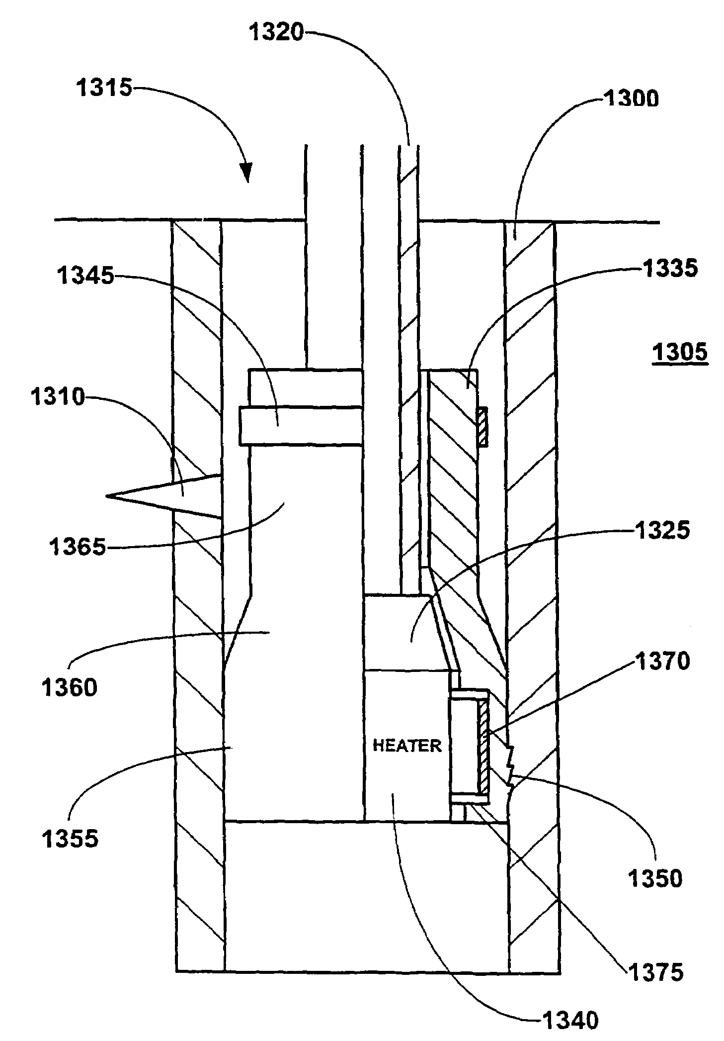
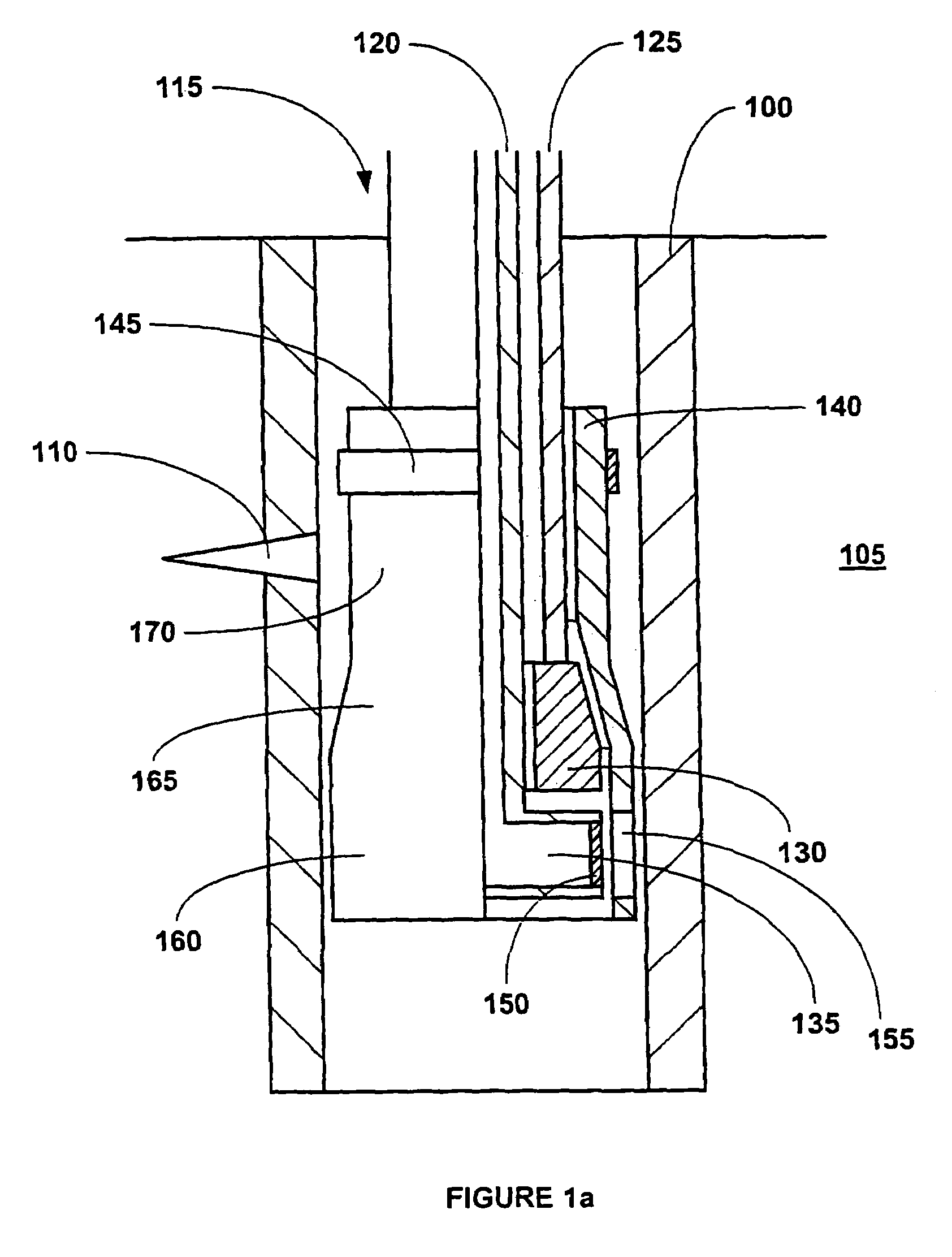
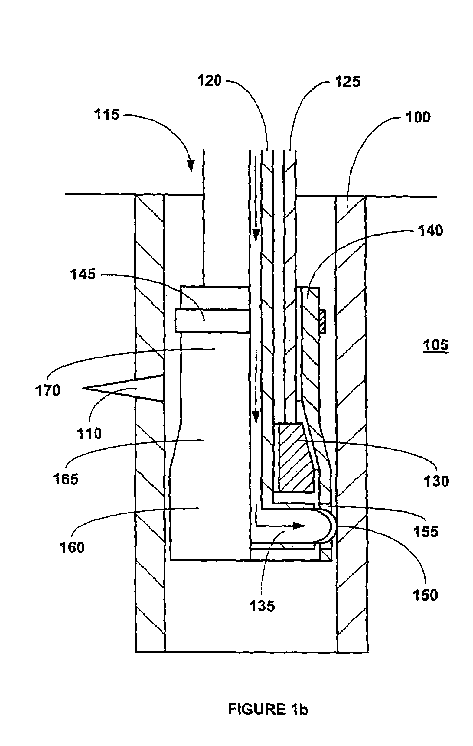
[0151]A method and apparatus for coupling tubular members to a preexisting structure is provided. In an exemplary embodiment, the tubular members are coupled to the preexisting structure by radially expanding the tubular members into contact with the preexisting structure. In an exemplary embodiment, the tubular members are radially expanded by anchoring one end of the tubular members to the preexisting structure and then pulling an expansion cone through the tubular members. In this manner, the tubular members are radially expanded and coupled to the preexisting structure.
[0152]Referring initially to FIGS. 1a, 1b, 1c, 1d, 1e, 1f and 1g, an exemplary embodiment of a method and apparatus for coupling an expandable tubular member to a preexisting structure will be described. Referring to FIG. 1a, a wellbore casing 100 is positioned within a subterranean formation 105. The wellbore casing 100 may be positioned in any orientation from the vertical direction to the horizontal direction. ...
PUM
Property
Measurement
Unit
distance
aaaaa
aaaaa
radial contact pressures
aaaaa
aaaaa
viscosity
aaaaa
aaaaa
Abstract
An apparatus and method for coupling a tubular member to a preexisting structure. The tubular member is anchored to the preexisting structure and an expansion member is displaced relative to the tubular member to radially expand the tubular member.
Description
CROSS REFERENCE TO RELATED APPLICATIONS[0001]This application is a divisional of U.S. application Ser. No. 10 / 303,992, filed Nov. 22, 2002, which is based on a National Phase of the International Application No. PCT / US01 / 19014, filed Jun. 12, 2001, which is based on U.S. Provisional Application Ser. No. 60 / 212,359, filed on Jun. 19, 2000, the disclosure of which is incorporated herein by reference.[0002]This application is a divisional of U.S. application Ser. No. 10 / 303,992, filed Nov. 22, 2002, which was a continuation-in-part of the following co-pending patent applications: (1) U.S. Pat. No. 6,561,227, which was filed as U.S. utility patent application Ser. No. 09 / 852,026, filed on May 9, 2001, which was a division of U.S. Pat. No. 6,497,289, which was filed as U.S. utility patent application Ser. No. 09 / 454,139, filed on Dec. 3, 1999, which claimed the benefit of the filing date of U.S. provisional patent application No. 60 / 111,293, filed on Dec. 7, 1998; (2) U.S. utility patent...
Claims
Application Information
Patent Timeline
Application Date:The date an application was filed.
Publication Date:The date a patent or application was officially published.
First Publication Date:The earliest publication date of a patent with the same application number.
Issue Date:Publication date of the patent grant document.
PCT Entry Date:The Entry date of PCT National Phase.
Estimated Expiry Date:The statutory expiry date of a patent right according to the Patent Law, and it is the longest term of protection that the patent right can achieve without the termination of the patent right due to other reasons(Term extension factor has been taken into account ).
Invalid Date:Actual expiry date is based on effective date or publication date of legal transaction data of invalid patent.