Chemical/biological hazard trigger with automatic mail piece tagging system and method

a technology of chemical/biological hazard and automatic mail piece tagging, which is applied in the field of system and method for detecting hazardous materials inside mail and marking them, can solve the problems of requiring manual process, requiring manual process, and requiring manual process, etc., and achieves the effect of time-consuming and difficult manual process

Inactive Publication Date: 2007-06-19
LOCKHEED MARTIN CORP
View PDF17 Cites 8 Cited by
  • Summary
  • Abstract
  • Description
  • Claims
  • Application Information

AI Technical Summary

Benefits of technology

[0023]A mail piece that causes a trigger event is typically being transported at high speed by a postal processing machine. Locating the exact mail pieces that may be responsible for the event can be a difficult and time-consuming manual process. The present invention provides a simple means of locating the suspect mail pieces, and directly links specific trigger parametric data to the suspect mail pieces, preserving the chain of evidence and associated forensic data.
[0024]The present invention combines real time trigger technology with high-speed inkjet printing. The bar code provides a means to rapidly identify mail pieces being processed at the time of the trigger event and correlating the mail piece to trigger parameters preserving the chain of evidence. The bar code can be used to uniquely divert mail pieces that are identified as potentially hot either immediately or after off-line second tier analysis.

Problems solved by technology

Barcodes currently applied to mail pieces by the USPS for sorting purposes are done at a point down stream from the trigger detection point, also these bar codes are not suitable for encoding trigger parametric data that is helpful for forensic purposes.
Presently there is apparently no automatic means of uniquely marking suspect mail pieces.
Locating the exact mail pieces that may be responsible for the event can be a difficult and time-consuming manual process.

Method used


Image

  • Chemical/biological hazard trigger with automatic mail piece tagging system and method
  • Chemical/biological hazard trigger with automatic mail piece tagging system and method
  • Chemical/biological hazard trigger with automatic mail piece tagging system and method

Examples


Embodiment Construction

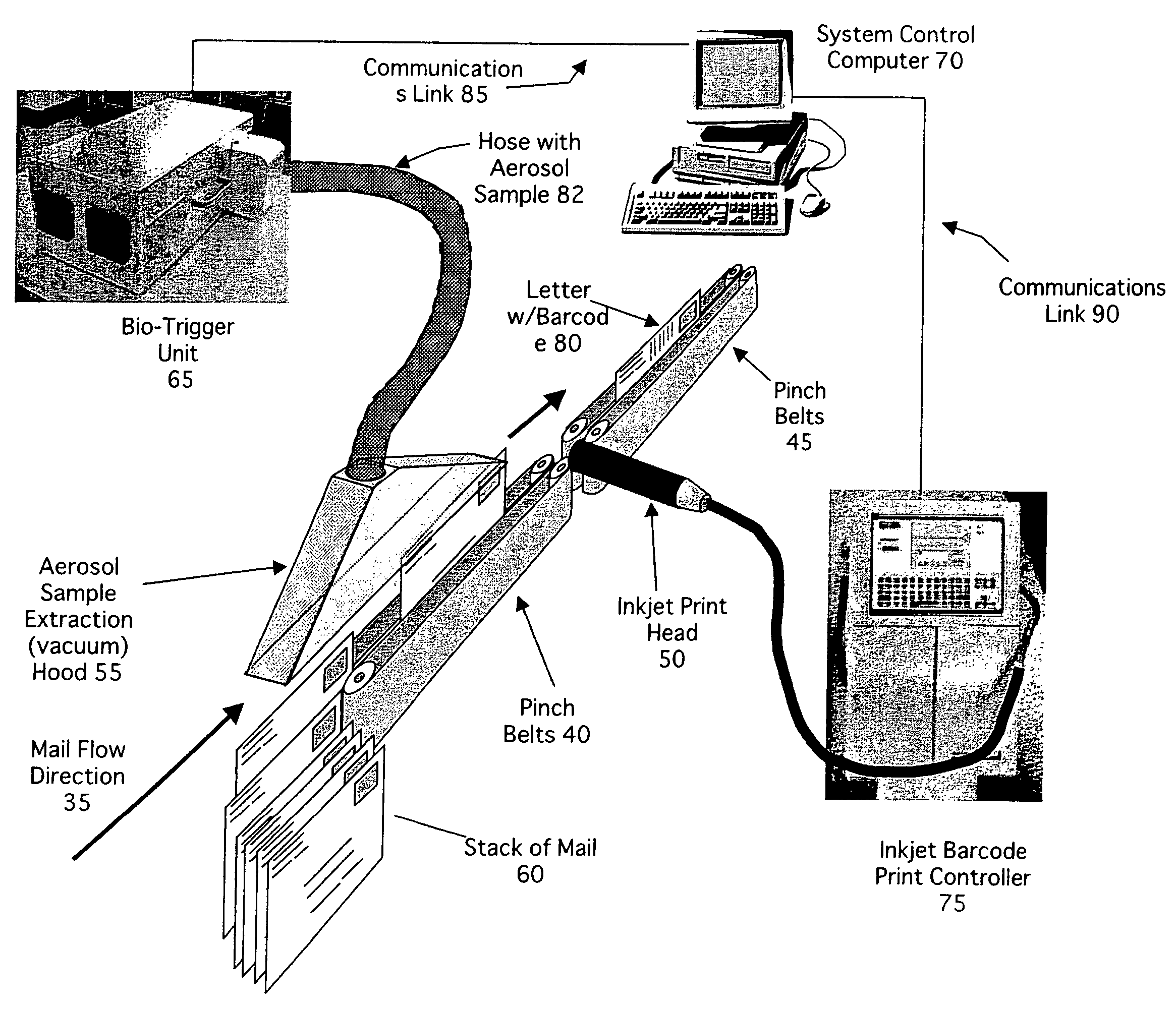
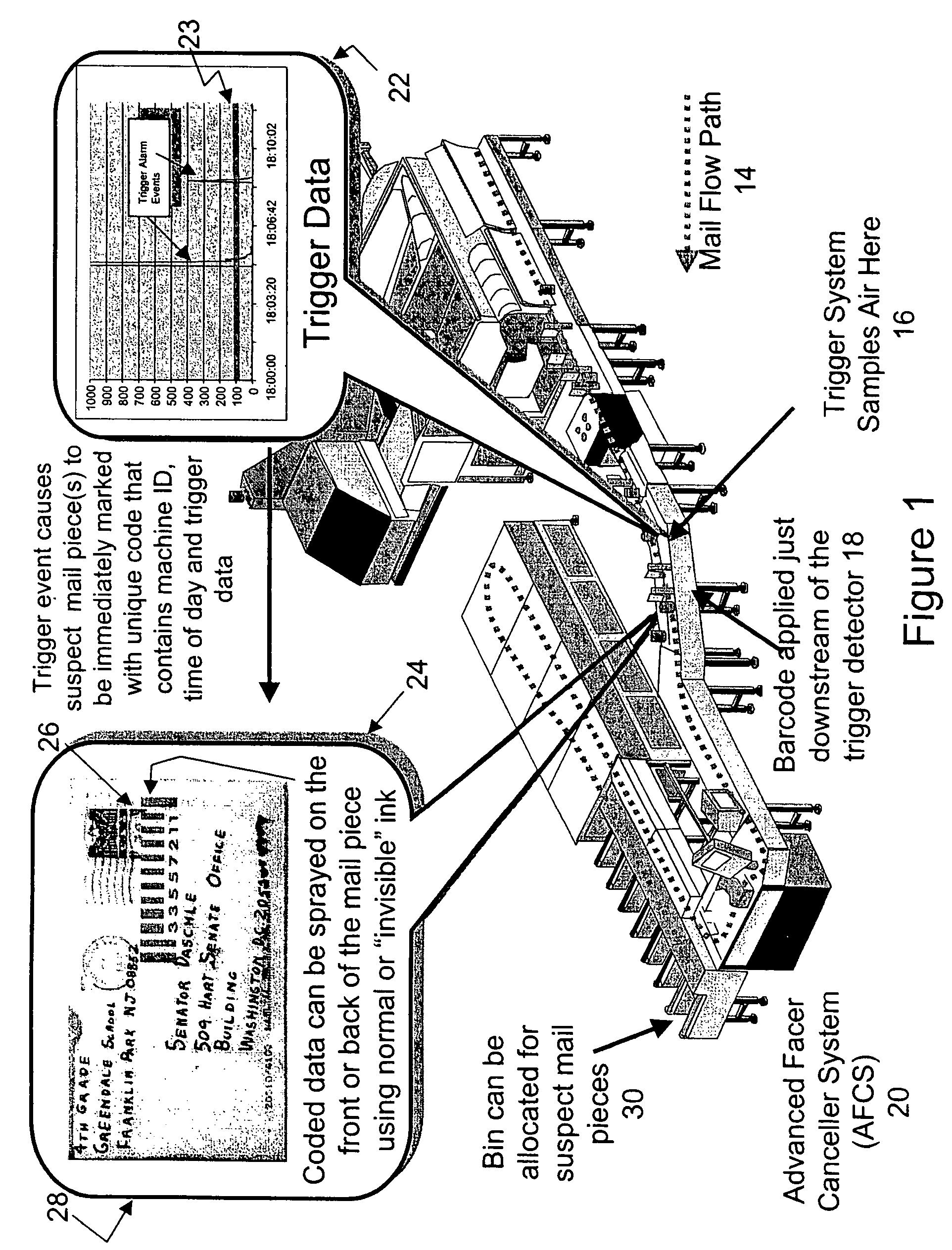
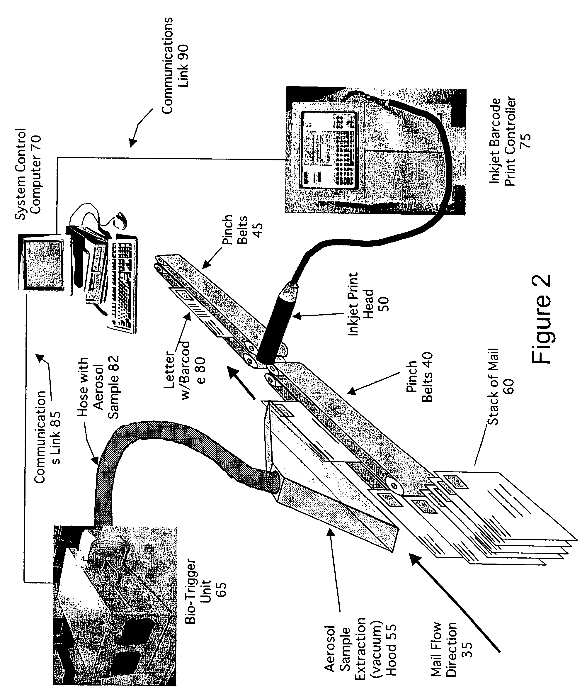
[0029]The present invention is arranged to work in conjunction with a chemical or biological hazard detection trigger attached to postal mail handling equipment. Such equipment is known in the prior art. In accordance with the present invention suspect mail pieces are marked, on-the-fly, with a unique barcode when a triggering event is detected. The bar code marking can be done with visible ink or with ink only visible under ultraviolet light. The bar code marking is used to rapidly identify suspect mail pieces, and correlate location, time of day and trigger operational response parameters to specific mail pieces being moved through the equipment at the time of the event.

[0030]Various aerosol particle detection trigger equipment is available that can be used to develop a system for detecting aerosolized pathogens that may be emitted from mail pieces during processing. For example, as mail is fed into an automatic mail processing machine, it is normally trapped between a pair of pin...


PUM


Abstract

Apparatus and method for detecting and identifying hazardous material in a mail stream in which hazardous particulates or material in or on mail pieces in a mail stream are detected and the mail piece bearing the hazardous material is identified. A bar code applicator applies a unique bar code to the wrapper of each mail piece identified as potentially containing hazardous material. The bar code applicator is an ink jet which applies the bar code on-the-fly. The bar code applied is encoded with specific information about the detection parameters at the time of the event in addition to specific information about the date, time of day, machine identification, temperature and humidity conditions, etc. present at the time of the event.

Description

CROSS-REFERENCE TO RELATED APPLICATIONS[0001]The present application is related to an application entitled Postal Image Augmented Bio-warfare Aerosolized Agent Trigger filed on the same date as the present application, and having one common inventor, and the content thereof is hereby incorporated herein by reference.BACKGROUND OF THE INVENTION[0002]The present invention relates to a system and method for detecting hazardous materials on or inside articles and, more particularly, to a system and method for detecting hazardous materials inside mail and marking them.[0003]All economies depend upon the physical shipment of materials for their functioning including the shipment of mail, merchandise, raw materials, and other goods.[0004]In some circumstances, it is desirable to subject the goods to some type of inspection to determine the presence of hazardous or impermissible materials, including biological and chemical materials. In general, sophisticated sensing systems are known for t...

Claims


Application Information

Patent Timeline
Patent Type & Authority Patents(United States)
IPC IPC(8): G06K7/10B07C1/00G06F17/00G06K15/00
CPCB07C1/00G07B17/00508G07B2017/00588
Inventor CRAIG, WILLIAM C.
Owner LOCKHEED MARTIN CORP
Why Eureka
Try Eureka