De-interlacing method, apparatus, video decoder and reproducing apparatus thereof

a video decoder and interlaced technology, applied in the direction of signal generators with optical-mechanical scanning, picture reproducers using projection devices, television systems, etc., can solve the problems of large errors in the pixel values obtained by the interpolation process, difficult to detect the edge direction, and complicated processing of interlaced video signals. achieve the effect of improving interpolation performance and easily and effectively detecting the edge location

Inactive Publication Date: 2007-06-19
SAMSUNG ELECTRONICS CO LTD
View PDF24 Cites 6 Cited by
  • Summary
  • Abstract
  • Description
  • Claims
  • Application Information

AI Technical Summary

Benefits of technology

[0010]The present invention provides a de-interlacing method and apparatus, and a video decoder and a reproducing apparatus using the de-interlacing method or apparatus capable of improving interpolation performance by easily and effectively detecting an edge located in a near-horizontal direction.

Problems solved by technology

However, processing for the interlaced video signal is relatively complicated because the interlaced video signal has two types of fields used to display a single image.
Therefore, if the interpolation process is performed based on only spatial adjacency without consideration of the edges, or the edge direction, the pixel values obtained by the interpolation process will have great errors.
However, since edges are far away from each other in the horizontal direction and near-horizontal directions, it is relatively difficult to detect the edge directions.
Therefore, the frame obtained by performing the interpolation process on fields having the edges located in the horizontal direction and near-horizontal directions has low quality of image due to inaccurate detection of the edge directions.
In particular, artifacts due to edges in the near-horizontal directions are more unpleasant to the eye than those in the near-vertical directions.
However, if the conventional method is applied to determine an edge in near-horizontal directions, an erroneous result may be obtained due to weak pixel correlation.
Although a large number of pixels may be used to increase the pixel correlation, errors in the edge detection and calculation amount may increase.

Method used


Image

  • De-interlacing method, apparatus, video decoder and reproducing apparatus thereof
  • De-interlacing method, apparatus, video decoder and reproducing apparatus thereof
  • De-interlacing method, apparatus, video decoder and reproducing apparatus thereof

Examples


Embodiment Construction

[0028]The present invention will now be described more fully with reference to the accompanying drawings, in which exemplary embodiments of the invention are shown. The invention may, however, be embodied in many different forms and should not be construed as being limited to the embodiments set forth herein; rather, these embodiments are provided so that this disclosure will be thorough and complete, and will fully convey the concept of the invention to those skilled in the art. In the drawings, the thicknesses of layers and regions are exaggerated for clarity.

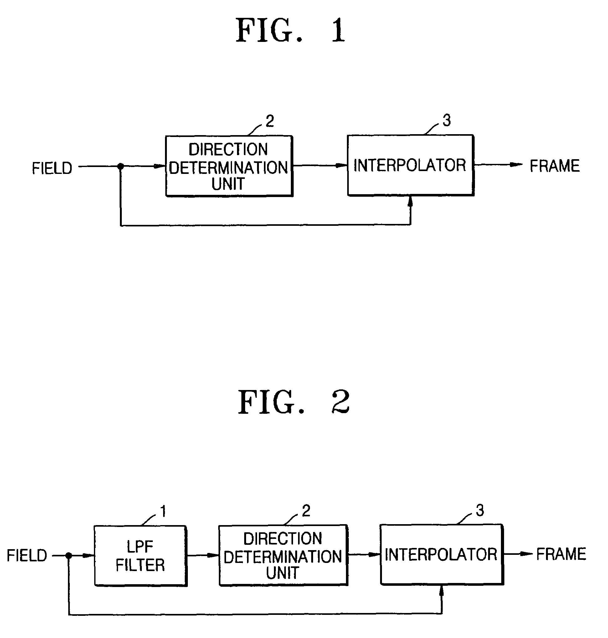
[0029]FIG. 1 is a block diagram illustrating a de-interlacing apparatus according to an embodiment of the present invention.

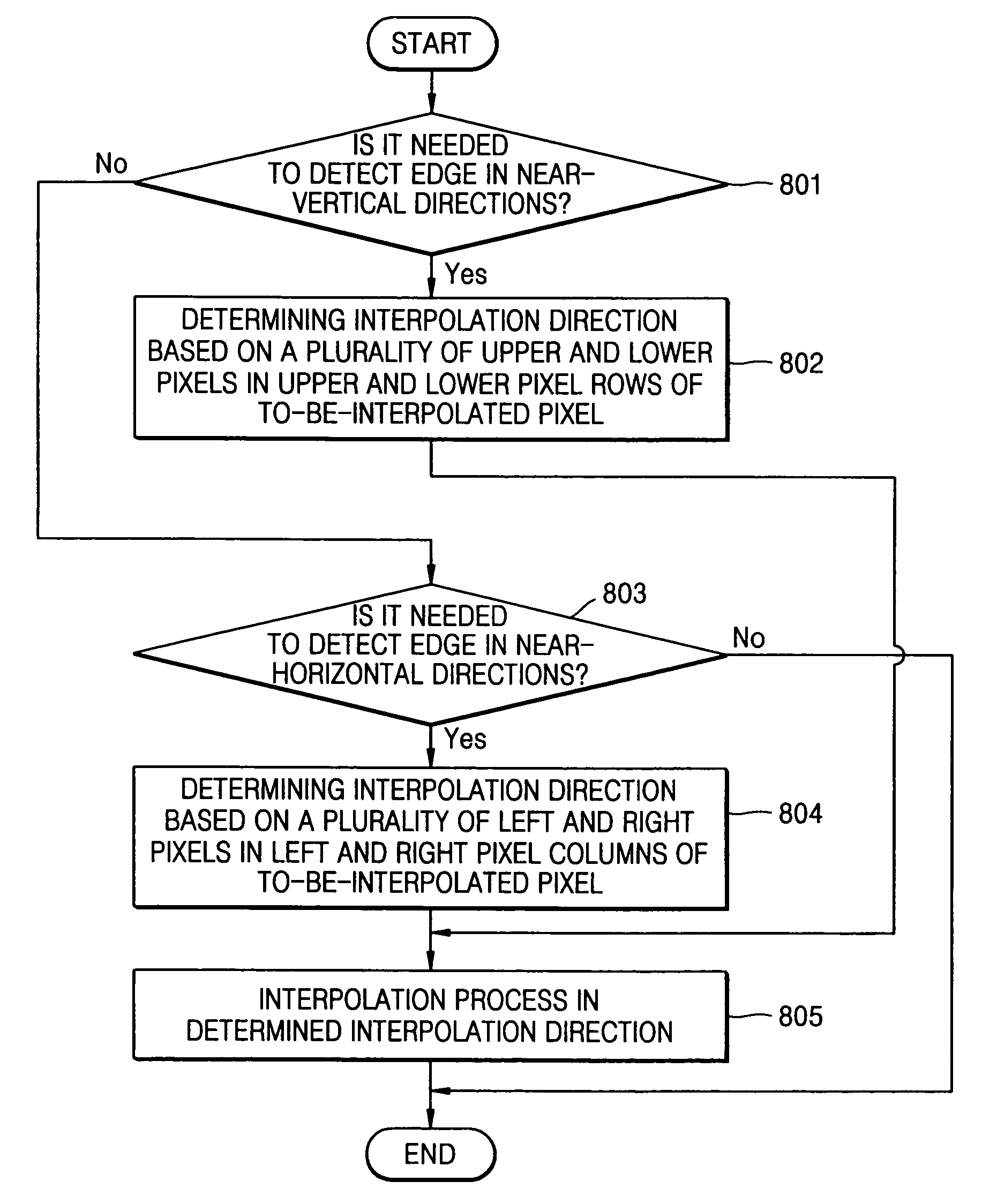
[0030]The de-interlacing apparatus comprises a direction determination unit 2 and an interpolator 3, which are used to convert an interlaced video signal into a progressive video signal. The direction determination unit 2 determines an edge direction, that is, an interpolation direction used for an inter...


PUM


Abstract

A de-interlacing method and apparatus, and a video decoder and a reproducing apparatus using the de-interlacing method or apparatus are provided. The de-interlacing method includes the steps of: (a) determining an interpolation direction based on a plurality of left and right pixels in left and right pixel columns located at left and right sides of the to-be-interpolated pixel, respectively; and (b) obtaining an interpolated pixel value by performing an interpolation process in a determined interpolation direction. According to the de-interlacing method, it is possible to improve interpolation performance by easily and effectively detecting an edge located in a near-horizontal direction without increasing calculation amount.

Description

BACKGROUND OF THE INVENTION[0001]This application claims the priority of Korean Patent Application No. 2003-39349, filed on Jun. 18, 2003, in the Korean Intellectual Property Office, the disclosure of which is incorporated herein in its entirety by reference.[0002]1. Field of the Invention[0003]Apparatuses and methods consistent with the present invention relate to a de-interlacing method of converting an interlaced video signal into a progressive video signal, an apparatus therefor, a video decoder, and a reproducing apparatus.[0004]2. Description of the Related Art[0005]In general, a video signal is implemented in an interlaced or progressive format. An interlaced video signal comprises a plurality of fields. A progressive video signal comprises a plurality of frames. One frame can be constructed by alternately inserting one type fields between the other type fields. In comparison with the progressive video signal, the interlaced video signal shows a high quality image with small ...

Claims


Application Information

Patent Timeline
Patent Type & Authority Patents(United States)
IPC IPC(8): H04N7/01H04N5/44
CPCH04N7/012H04N7/01
Inventor SONG, BYUNG-CHEOL
Owner SAMSUNG ELECTRONICS CO LTD
Why Eureka
Try Eureka