
Method and device for generating an output signal as a mathematical function of an input signal

a digital input signal and mathematical function technology, applied in the field of methods and devices for generating digital output signals as mathematical functions of digital input signals, can solve the problems of inconvenient interpolation of indices, high hardware cost, and inability to accurately calculate function values in real time, and achieve very low accuracy, so as to achieve minimal linear interpolation, the effect of reducing the loss of accuracy

Inactive Publication Date: 2007-06-19
ROHDE & SCHWARZ GMBH & CO KG
View PDF10 Cites 0 Cited by
  • Summary
  • Abstract
  • Description
  • Claims
  • Application Information

AI Technical Summary

Benefits of technology

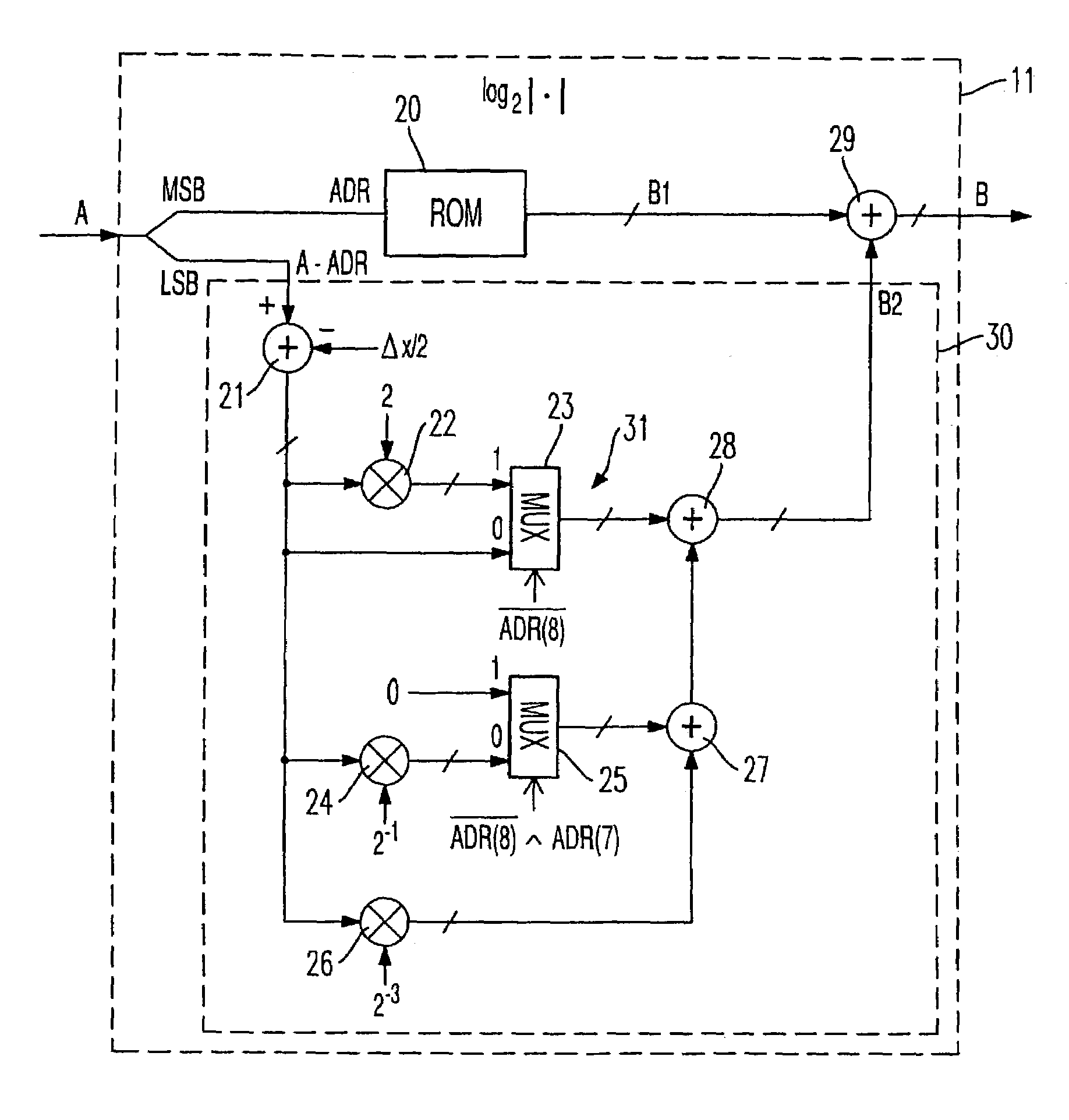
[0008]A linear interpolation among the tabulated function values is preferably used. A considerable simplification can be achieved either by using a uniform, constant increase for the linear interpolation over the entire compressed argument range or by dividing the compressed argument range into a few segments, within each of which a constant increase is used for linear interpolation. In contrast to a linear interpolation in which the increase is determined separately on the basis of the difference quotients at each index, a considerable simplification is achieved with the implementation of linear interpolation. Since the permissible argument range of the tabulated mathematical function is greatly reduced compared to the permissible range of values of the input signal, the losses of accuracy entailed by this simplification of linear interpolation are minimal.
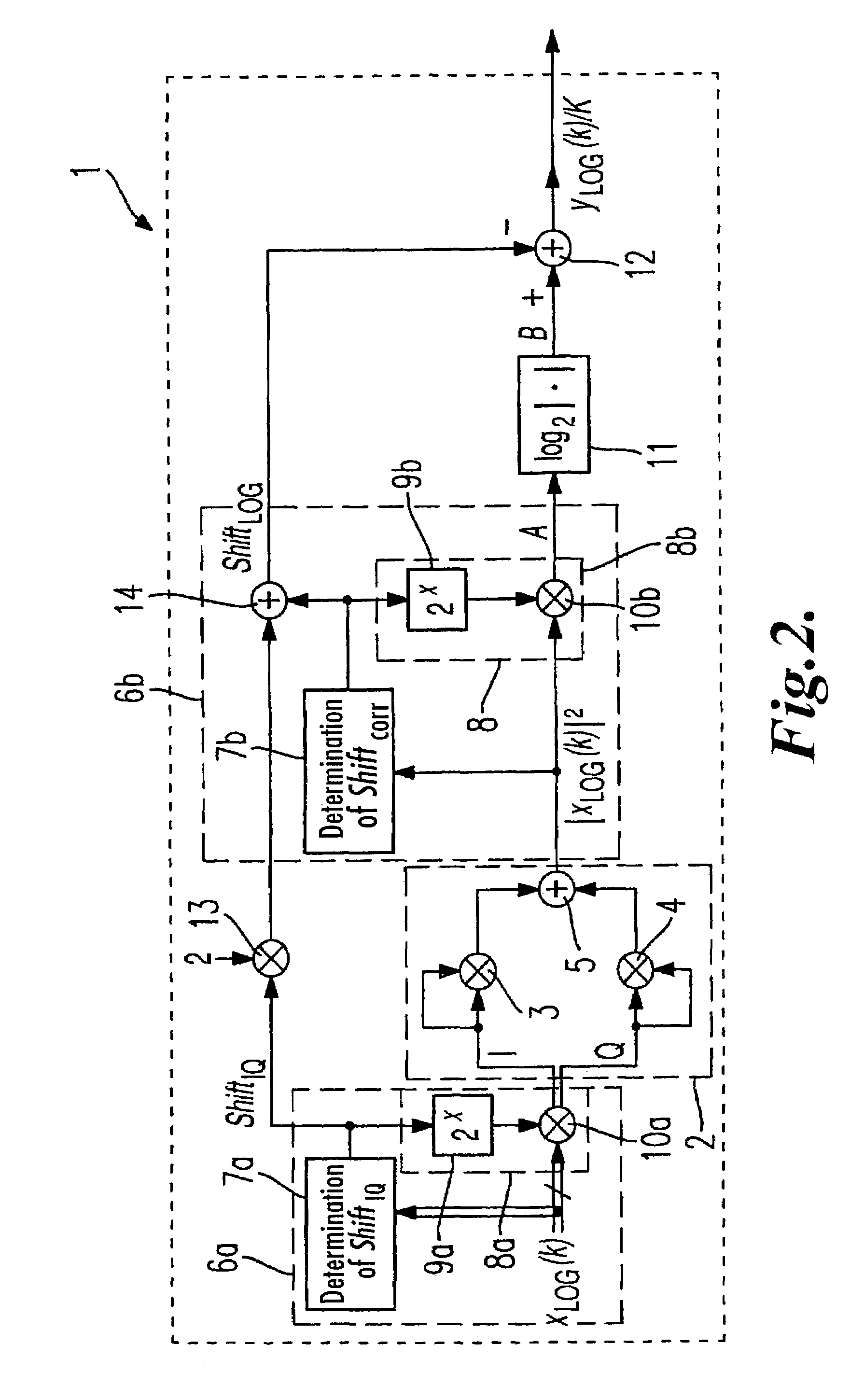
[0009]If the square of the magnitude of a complex input signal is to be calculated first, it is advantageous to perform a coarse amplification or attenuation of the input signal, at least in part, even before the magnitude of the signal is squared, and after said squaring to perform a fine amplification or attenuation, where appropriate, and adjust the correction signal accordingly.

Problems solved by technology

Calculating function values in real time is so hardware-intensive as to render it ordinarily impracticable.
If one table is stored for all the possible values of the input signal, either the storage requirements will be high, or the indices in the table will be so far apart that either the accuracy achieved will be very low or the interpolation method will require much more intensive use of resources to interpolate between indices.

Method used


Image

  • Method and device for generating an output signal as a mathematical function of an input signal
  • Method and device for generating an output signal as a mathematical function of an input signal
  • Method and device for generating an output signal as a mathematical function of an input signal

Examples


Embodiment Construction

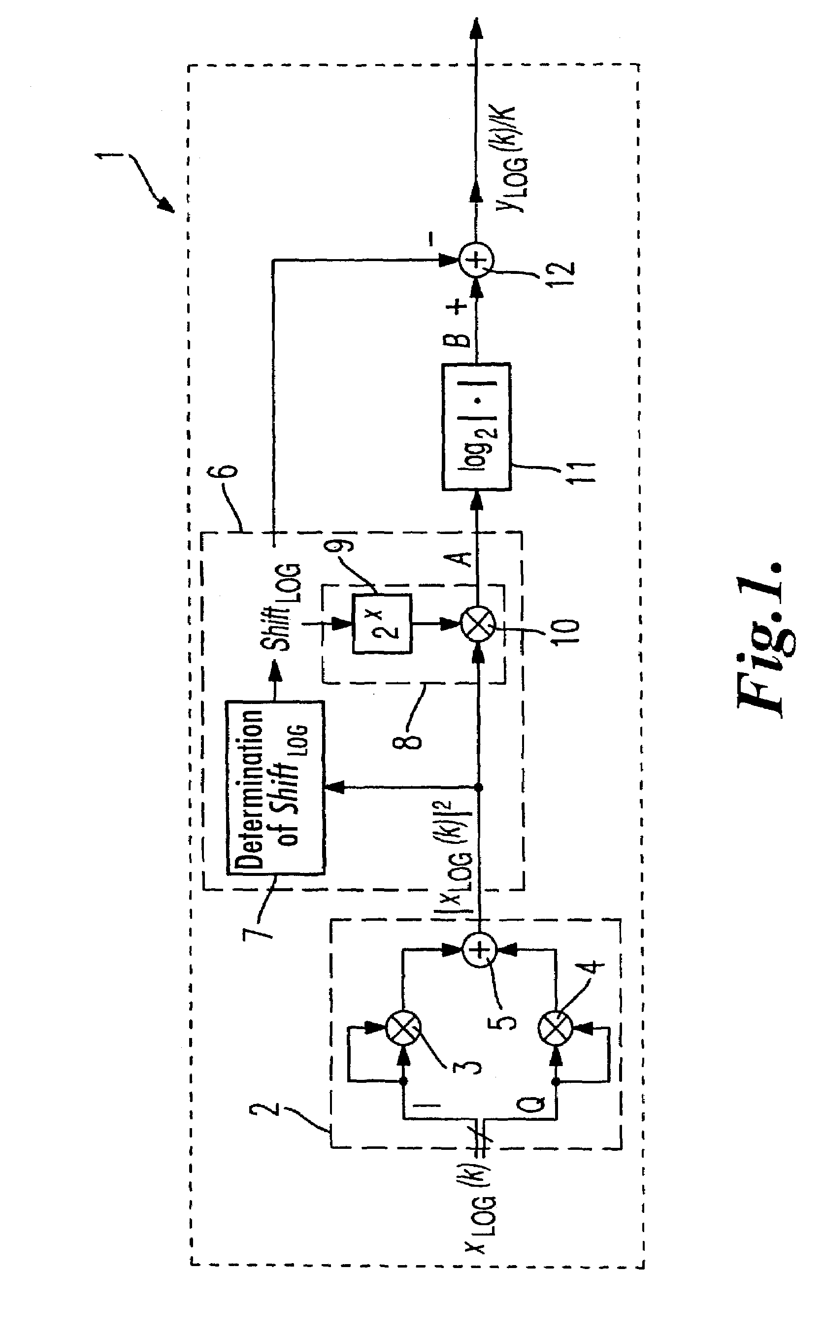
[0018]FIG. 1 shows a first exemplary embodiment of the device 1 according to the invention for implementing the method of the invention. In the exemplary embodiment shown, the device 1 serves to generate, from a digital input signal xLOG(k) consisting of a scanning sequence, a digital output signal yLOG(k) / K also consisting of a scanning sequence, the scanning values of output signal yLOG(k) / K being the logarithm to the base 2 of the scanning values of input signal xLOG(k). The logarithm to the base 2 differs from the logarithm to the base 10 only by the constant K, and thus the scanning sequence yLOG(k) represents the logarithm to the base 10 of the scanning sequence of input signal xLOG(k). The invention lends itself to any desired mathematical functions, particularly monotonic functions, and is not limited to applications involving logarithms.

[0019]In the exemplary embodiment shown in FIG. 1, in a square generator 2, first, the square of the magnitude of the input signal xLOG(k) ...


PUM


Abstract

A device (1) for generating a digital output signal yLOG(k) / K) as a mathematical function of a digital input signal (xLOG(k)) includes a level-changing device (6), which by amplifying or attenuating the input signal (xLOG(k)) generates a first intermediate signal (A) that falls within a compressed argument range of the mathematical function and a correction signal (shiftLOG) dependent on the amplification or attenuation of the input signal (xLOG(k)). Tabulated function values of the mathematical function are stored at or between indices in a storage device (11). The tabulated function values (B1) are read from the storage device (11) in dependence on the first intermediate signal (A), and a second intermediate signal (B) is generated in dependence on the read tabulated function values (B1). The correction signal (shiftLOG) is subtracted from the second intermediate signal (B) in a subtractor (12) to yield the digital output signal yLOG(k) / K).

Description

CROSS-REFERENCE TO RELATED APPLICATION[0001]This application claims priority benefit under 35 U.S.C. § 119 to German Patent Application No. 101 63 350.5 filed Dec. 21, 2001, which is incorporated herein by reference.FIELD OF THE INVENTION[0002]The invention concerns a method and a device for generating a digital output signal as a mathematical function of a digital input signal, together with a computer program for implementing the method.BACKGROUND OF THE INVENTION[0003]By way of example, there are applications in which the logarithm of the magnitude of a complex digital input signal consisting of a real component I and an imaginary component Q must be used to produce, for example, a logarithmically scaled controlled variable. Common practice heretofore has been either to calculate the function value, for example by iterative methods, or to keep the function values in readiness in extensive tables and retrieve them according to the value of the input signal. Calculating function va...

Claims


Application Information

Patent Timeline
Patent Type & Authority Patents(United States)
IPC IPC(8): G06F1/02G06F7/00G06F7/556G06F17/17G06F17/10
CPCG06F7/556
Inventor FREIDHOF, MARCUS
Owner ROHDE & SCHWARZ GMBH & CO KG
Learn More