
Auto hammock rocker

a technology of auto-hammam and rocker, which is applied in the direction of beds, travelling objects, sofas, etc., can solve the problems of small spring likely not having enough energy to rock a hammock, the rocker to exhibit movement, and the small spring likely not providing rocking movemen

Inactive Publication Date: 2007-06-26
DREVITSON KYLE C
View PDF20 Cites 23 Cited by
  • Summary
  • Abstract
  • Description
  • Claims
  • Application Information

AI Technical Summary

Benefits of technology

[0021]The present invention provides a hammock rocking machine comprising a container, a periodically reversing geared motor, and an oscillating portion having a connection member adapted to be attached to a hammock by an attachment portion. The hammock rocking machine has one end connected to a fixed stationary object. The other end of the hammock rocking machine is attached to a conventional hammock. The hammock rocking machine has a large torsional spring attached to the shaft of the geared motor while the other end of the spring is attached to a conventional hammock. When an occupant reclines on and rocks the hammock initially, the torsional spring, together with the weight of the recumbent occupant, creates a natural harmonic oscillator having a characteristic oscillation periodicity. The geared electrical motor, controlled by the electrical circuit, is powered by house current or batteries. It is turned on by a pressure switch incorporated in the hammock, which is closed when the hammock becomes occupied. The motor driving circuit comprises electrical driving circuitry, which periodically reverses the direction of rotation of movement of the motor, while the motor current is monitored. This period of oscillation is gradually decreased from a long period to a value that synchronizes with the periodicity of oscillation of the natural frequency of oscillation of the hammock, at which point the current needed to drive the electrical motor is the lowest.

Problems solved by technology

Oftentimes such prior art devices have too little energy available to sustain the rocking motion, thereby causing the rocker to exhibit movement that is inconsistent with the desired rocking motion of the user.
Many of the devices require some form of initiation and do not provide rocking movement automatically when the user climbs onto the hammock.
The small spring likely has insufficient energy to rock a hammock when weighted by an occupant.
Power requirements for the system make it unlikely that rocking motion would be imparted to a hammock when the occupant is an adult.
The swinging device disclosed by the '635 patent disclosure is incapable of rocking a hammock occupied by an adult.
The compound motion generated by the motor drive provides unexpected movement that is unsuited for a conventional hammock.
The movable ferromagnet becomes stuck within the coil, making it impossible to start the oscillation.
The coil is likely burn out due to prolonged passage of current.
The device has insufficient power to be used on a conventional hammock occupied by an adult.
It is unsuited for rocking a hammock occupied by an adult.
These cables cannot be easily attached to a conventional hammock, which is generally suspended from two fixed locations.
Therefore, this device is unsuited to create rocking motion for a conventional hammock.
The rubber bands are generally not strong and elliptical pulleys only generate limited tension in the resilient belts.
Therefore, a belt tensioned by an elliptical pulley cannot be used to rock a hammock.
The elliptical pulleys are on a separate drive shaft and this cannot be provided for a hammock attached between two fixed supports.
Due to mechanical complexities of this device it is usable with a conventional porch swing, but is not usable with a conventional hammock that is attached to two fixed locations.

Method used


Image

  • Auto hammock rocker
  • Auto hammock rocker
  • Auto hammock rocker

Examples


Embodiment Construction

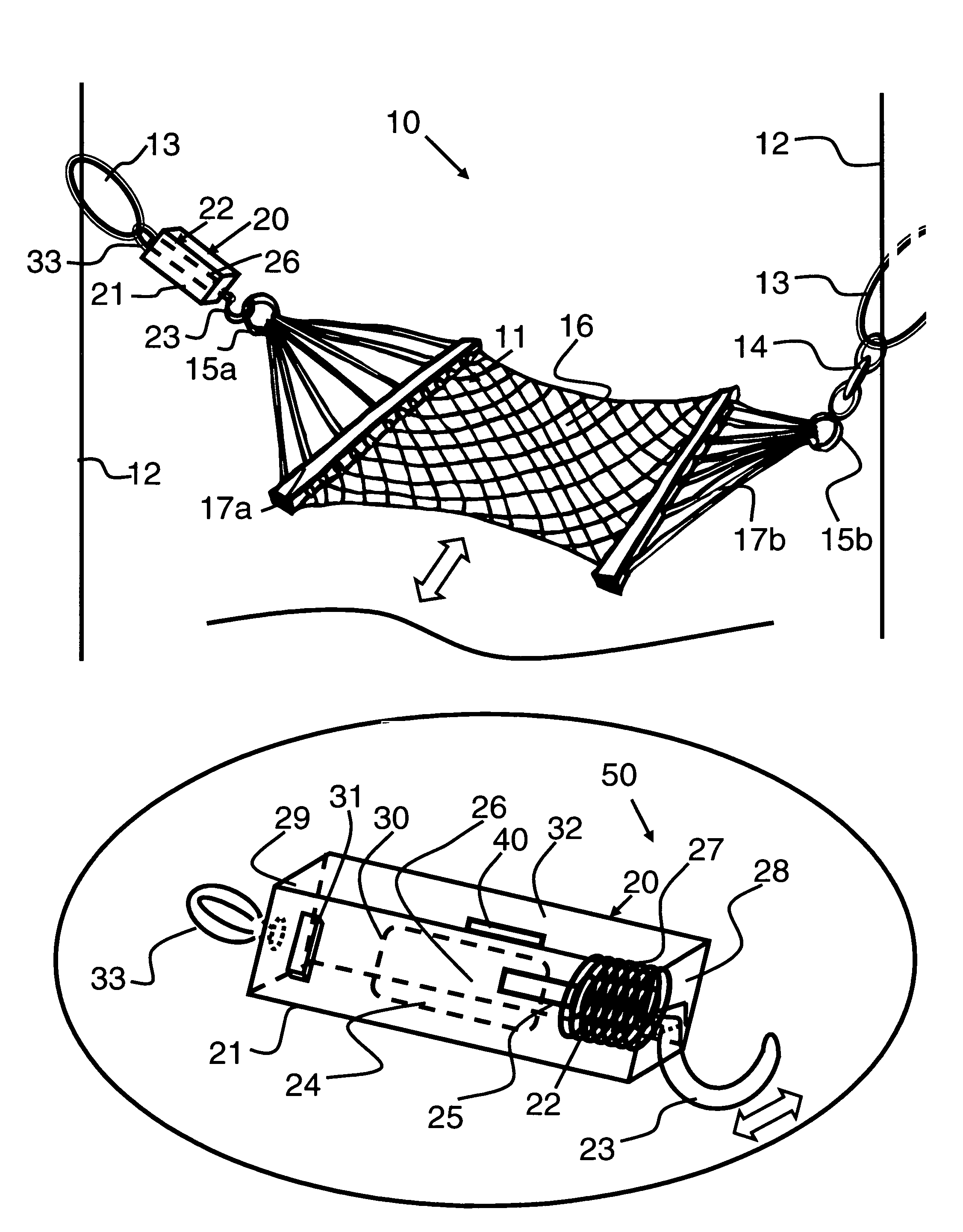
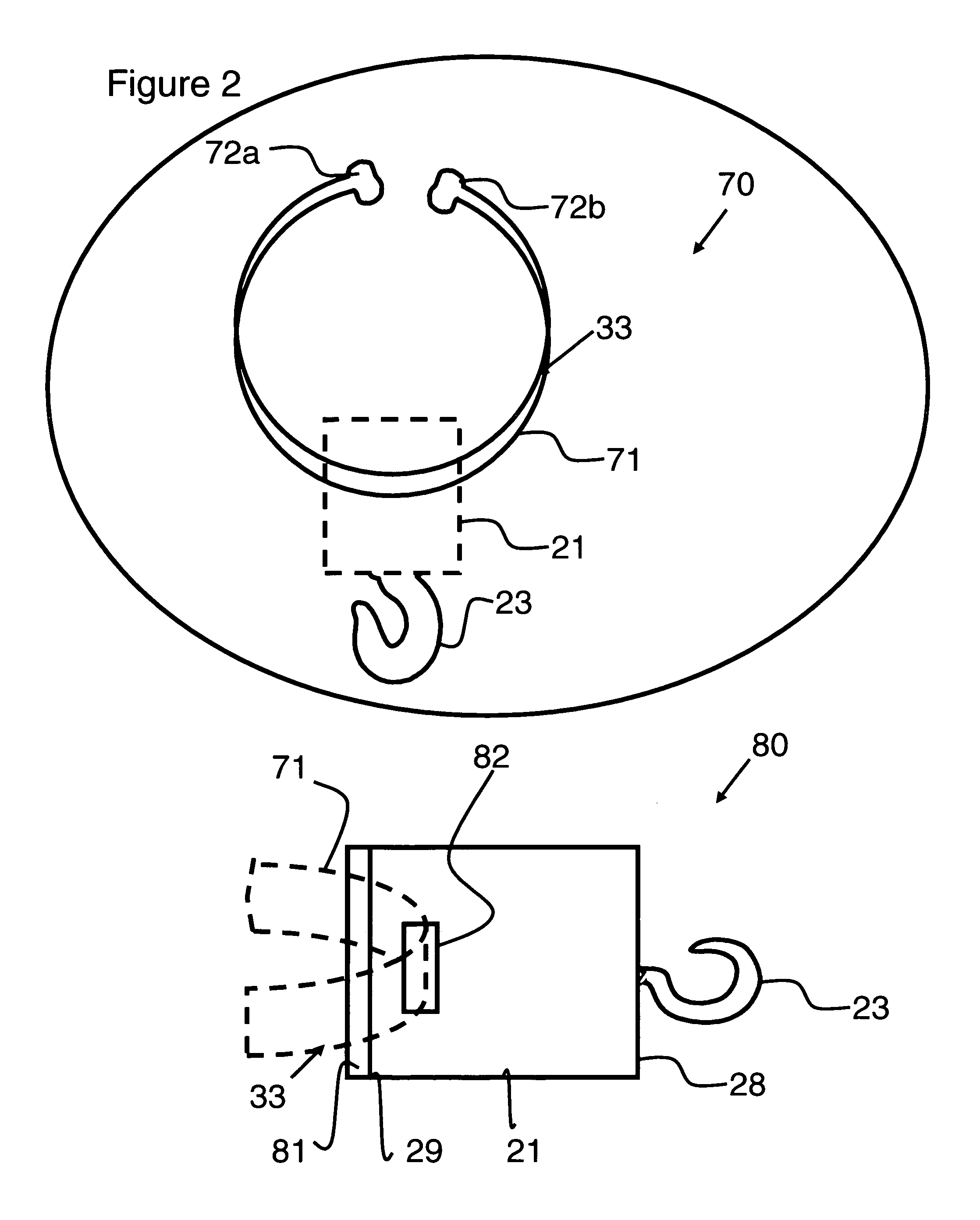
[0028]This invention relates to an Auto Hammock Rocker, which gently rocks a hammock occupant as soon as the hammock becomes occupied, thereby relaxing the occupant. A commonly known hammock is firmly attached to a container that is in turn firmly attached to a post or a tree or other stationary objects. The container has a top portion, a bottom portion and at least one side portion defining an internal compartment. The container has more than one side portion and may completely surround the internal compartment, if so desired. The internal compartment houses a periodically reversing geared motor, which may be powered by a battery or house current. The shaft of the geared motor rotates at a slow speed, delivering a high level of torque. The shaft of the geared motor is integrally connected to a torsional spring. The other end of the spring is connected to an arm which, in turn, is connected to the conventional hammock with a pressure switch. The torsional spring and the arm are refe...


PUM


Abstract

A rocking machine automatically imparts a continuous, rocking motion to an occupant recumbent on a hammock. One end of the rocking machine is attached to a fixed location. The other end of the rocking machine is attached to a conventional hammock, which is attached to a second fixed location. The rocking machine has a container that houses a periodically reversing geared motor. Operation of the motor is controlled by an electrical circuit having a shaft attached to one end of a torsional spring. The other end of the torsional spring is connected to the hammock. A pressure sensitive switch becomes actuated and moves to a closed position, enabling supply of power to the geared motor that initiates a continuous rocking motion, when the hammock becomes occupied. The electrical circuit provides periodically reversing oscillations while monitoring current to the motor, and decreases the period between oscillations until it matches the natural period of oscillation of the spring-occupant weight system. Motor current is thereby maintained at a decreased value, increasing the efficiency of energy transfer from the motor to rocking motion for said hammock.

Description

BACKGROUND OF THE INVENTION[0001]1. Field of the Invention[0002]The present invention relates to a motorized rocking machine for imparting reciprocal, oscillating motion to a hammock; and more particularly, to motorized hammock rocker that automatically sustains the rocking motion of an occupant recumbent on a conventional hammock.[0003]2. Description of the Prior Art[0004]A variety of rockers have been contemplated in the art, enabling oscillating movement of baby carriages, swings, hammocks and the like. These devices include for example, electrical motor driven devices and energy storage devices having spring wound drivers. Oftentimes such prior art devices have too little energy available to sustain the rocking motion, thereby causing the rocker to exhibit movement that is inconsistent with the desired rocking motion of the user. Many of the devices require some form of initiation and do not provide rocking movement automatically when the user climbs onto the hammock.[0005]U.S. ...

Claims


Application Information

Patent Timeline
Patent Type & Authority Patents(United States)
IPC IPC(8): A45F3/22
CPCA45F3/22
Inventor DREVITSON, KYLE C.
Owner DREVITSON KYLE C
Learn More