Door closer power adjusting device

a technology of power adjustment device and door closer, which is applied in the direction of wing opener, multi-purpose tools, construction, etc., can solve the problem of difficulty for all persons to open the door against the normal high power of the closer, and achieve the effect of opening more easily

Active Publication Date: 2007-06-26
C R LAURENCE
View PDF17 Cites 33 Cited by
  • Summary
  • Abstract
  • Description
  • Claims
  • Application Information

AI Technical Summary

Benefits of technology

[0003]A drawback of a high powered door closer is that it may be difficult for all persons to open the door against the normal high power of the closer. For this reason, a device according to the present invention is provided to adjust the power of the door closer to a much lower power, upon receipt of a signal from such a user, so that the door can be opened more easily. After a set time, the power of the door closer will be returned to the higher power level to provide the security to the building or space normally provided by the closed door.

Problems solved by technology

A drawback of a high powered door closer is that it may be difficult for all persons to open the door against the normal high power of the closer.

Method used


Image

  • Door closer power adjusting device
  • Door closer power adjusting device
  • Door closer power adjusting device

Examples


Embodiment Construction

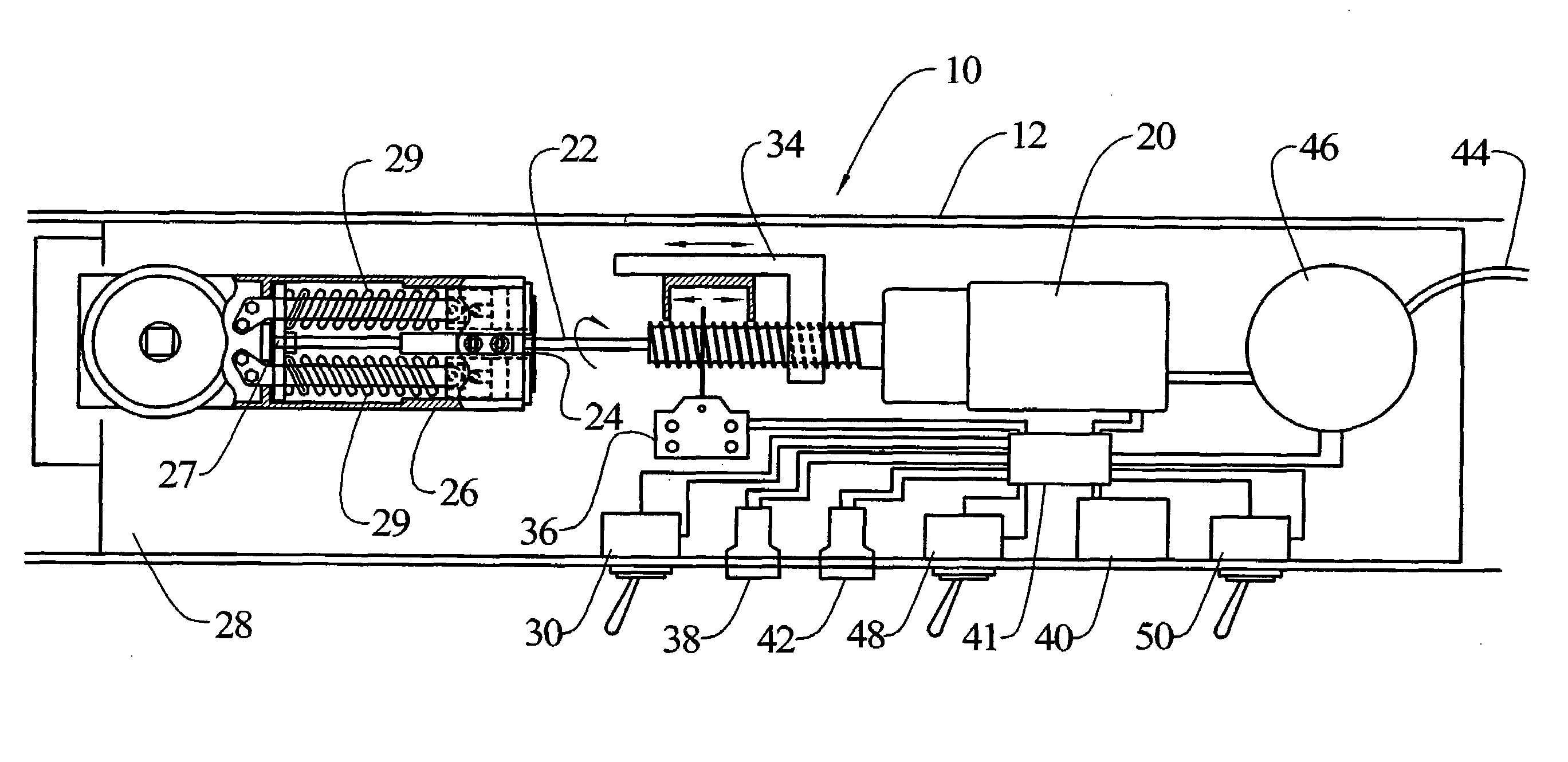
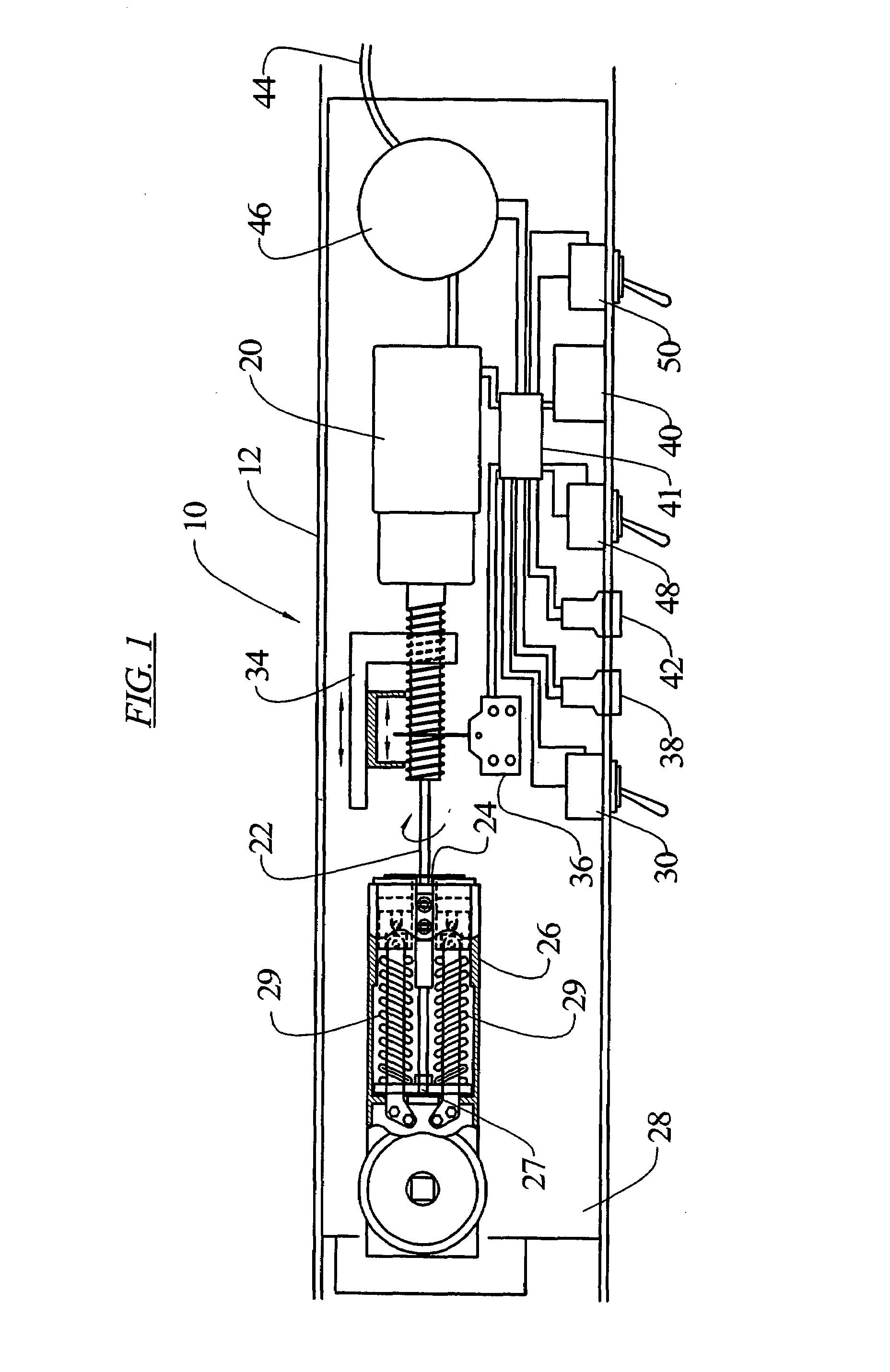
[0007]In an embodiment of the invention, as illustrated in FIG. 1, door closer power adjusting device 10 includes a housing 12 for accommodating a number of internal components. One of the components, a powered unit in the form of a high torque motor 20, such as a 12 volt portable drill motor, can be used to rotate a shaft 22 connected, via an appropriate interface, to a power adjustment screw 24 of a door closer 26. The motor 20 and shaft 22 can be located in a door transom 28 so that they are not visible to the user during normal usage. Other types of powered units may be utilized to move a plate 27 in the door closer 26 against which one or more springs 29 in the door closer are compressed, including other types of motors, gear arrangements, and hydraulic or pneumatic movable pistons which may move the plate directly without use of a rotatable adjustment screw.

[0008]A switch 30 may be provided to allow the user to activate the motor 20 to rotate the power adjustment screw 24 to l...


PUM


Abstract

A door closer power adjusting device for a door closer having a spindle driven by a compressed spring with a movable plate for adjusting spring compression, or with a screw for adjusting spring compression, between a high and low level of compression. A powered unit moves the plate in a first direction to achieve the low level of compression and in a second direction to achieve the high level of compression. A switch activates the powered unit in the first direction and a first switch is engaged when the spring is compressed to the low level of compression to deactivate the powered unit. A timing circuit activates the powered unit in a second direction after passage of a predetermined time. A second switch is engaged when the spring is compressed to the high level of compression to deactivate the powered unit.

Description

BACKGROUND OF THE INVENTION[0001]The present invention relates to spring powered door closers, such as disclosed in U.S. Pat. Nos. 3,246,362, 4,064,589, and 5,666,692, which disclosures are incorporated herein by reference. In such closers it is known that the closing power or force required to open the door against the spring force of the closer can be adjusted by providing greater or lesser compression of the springs in the closer. This can be accomplished by rotating a screw that moves a plate internally of the closer body that further compresses the spring, or allows the spring to expand, depending upon the direction of rotation of the screw. Such an arrangement is disclosed in the '692 patent.SUMMARY OF THE INVENTION[0002]The present invention allows the power of the closer to be adjusted by a user through the use of a powered arrangement, rather than through a manual operation by the user. Such a device is particularly useful to allow for greater accessibility to spaces closed...

Claims


Application Information

Patent Timeline
Patent Type & Authority Patents(United States)
IPC IPC(8): E05F3/00E05F11/00E05F1/10
CPCE05F1/105Y10T16/56Y10T16/577E05Y2900/132
Inventor BROWN, PETER EDWARDTOLEDO, GEORGE
Owner C R LAURENCE
Why Eureka
Try Eureka