
Token dispensing device with decreased loading on a token dispensing disk

a token and dispensing disk technology, applied in coin dispensers, instruments, textiles and paper, etc., can solve the problems of increasing the speed of the rotating disk, requiring a correspondingly higher amount of energy to operate, and high so as to reduce the load on the rotating disk

Inactive Publication Date: 2007-06-26
ASAHI SEIKO CO LTD
View PDF18 Cites 2 Cited by
  • Summary
  • Abstract
  • Description
  • Claims
  • Application Information

AI Technical Summary

Benefits of technology

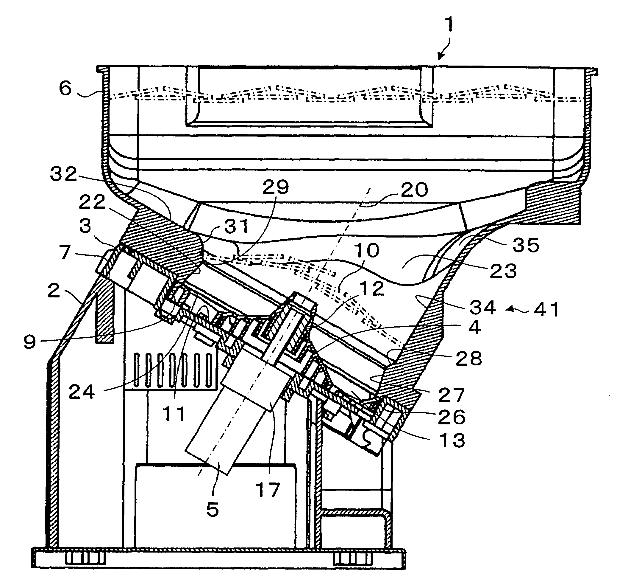
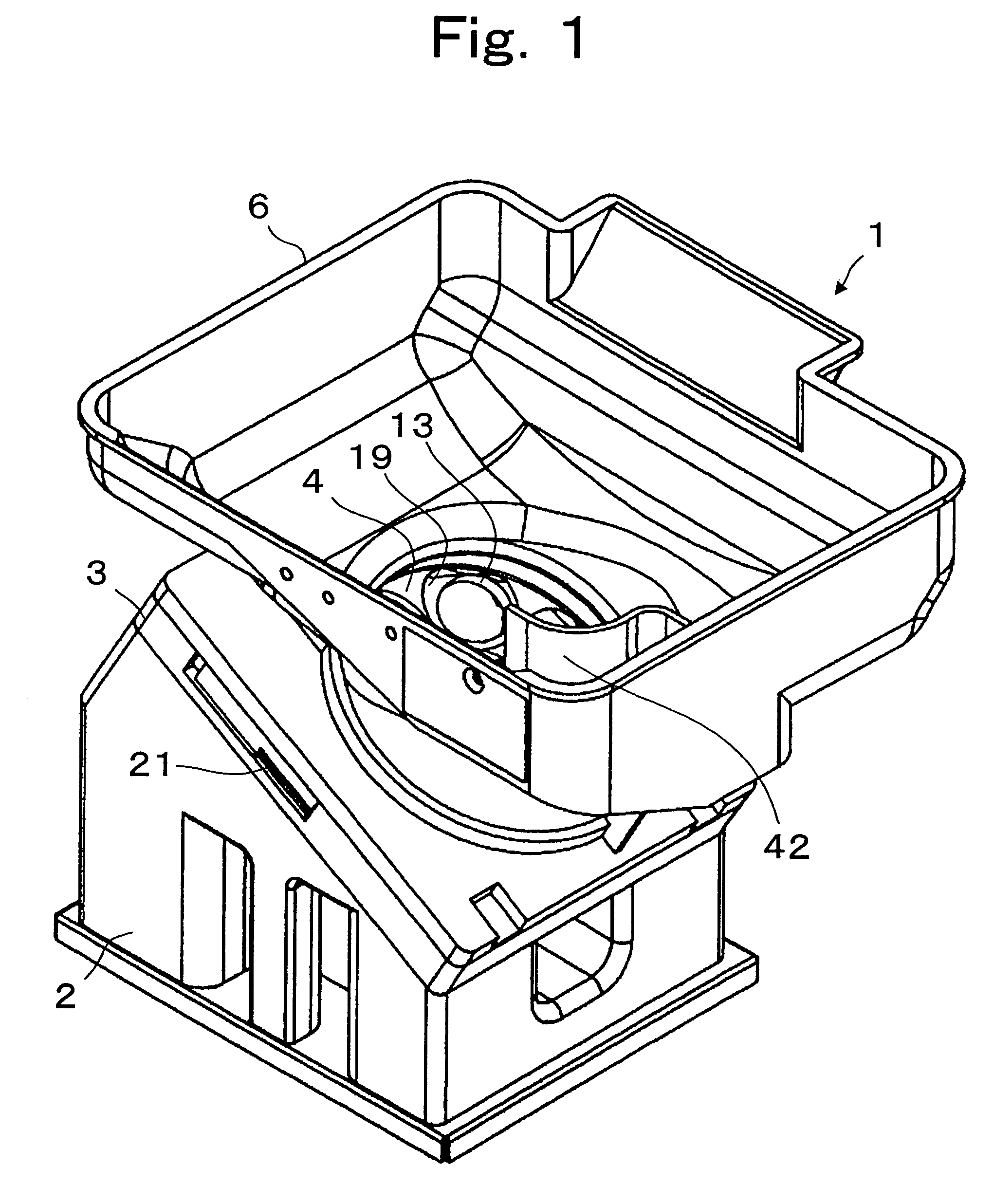
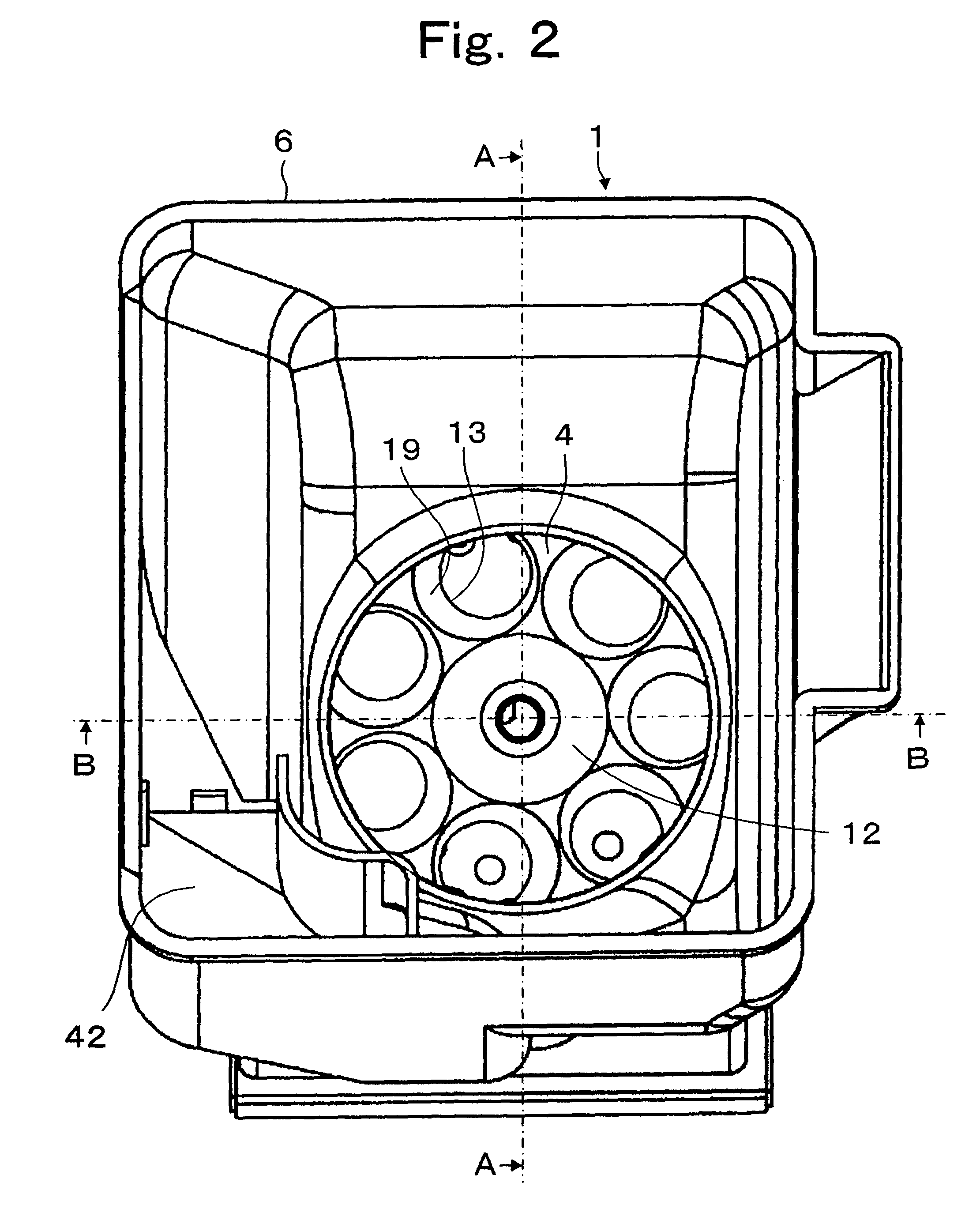
[0009]The present invention addresses the limitations of the prior art by providing a token dispensing device with a decreased load both in weight on the rotating disk as well as the load resistance to turning of the rotating disk. Aspects of the present invention also reduce the incidence of unwanted jamming. Some components of the present invention may be constructed from resin compounds, yielding efficient and inexpensive manufacturability.
[0011]The lower section of the storing bowl is fixed on the base plate and includes a narrowed circular convex section with a slanted enlarging section surface to allow tokens descending from the storing bowl in proximity to the convex section to partially rest upon the enlarging section and other tokens to create a loose bridge-like structure to impede or restrict the flow of tokens through the convex section, thereby creating a quasi-jamming condition. This quasi-jamming condition reduces the loading on the rotating disk thereby reducing the amount of energy consumed by the dispensing process.
[0012]The rotating disk has at least one through hole for retaining one or more tokens that are moved across the base plate and is dispensed. The surface of the rotating disk around the through hole has a cone-shaped hollow to permit tokens to more easily enter the through hole. The lower section of the storing bowl has a wider diameter below the narrowed circular convex section to extend beyond the outer edge of the through hole. The diameter of the narrowed circular convex section at the most narrow point does not extend beyond the outer edge of the through hole in order to create a conically tapered section where tokens can enter the through hole.
[0013]The rotating disk has a cone-shaped projection that extends above the narrowed circular convex section in order to agitate the descending tokens. The rotating disk is slanted at an angle from horizontal to further reduce the loading on the rotating disk.

Problems solved by technology

However, the structure of these dispensing devices were such that the load on the rotating disk was high, requiring a correspondingly higher amount of energy to operate.
Further, to increase the rate of dispensing required increasing the speed of the rotating disk, which required even more energy.
This is undesirable.
Further, as the rotating disk diameter grows, the angular force required to turn the loaded rotating disk is also increased, resulting in higher energy consumption.
This reduced the storage capacity as well as influenced the shape of the storing bowl, and was undesirable.
This obstacle both decreased the storage capacity as well as increased the incidence of undesired jamming.
The obstacle created a static jamming condition.

Method used


Image

  • Token dispensing device with decreased loading on a token dispensing disk
  • Token dispensing device with decreased loading on a token dispensing disk
  • Token dispensing device with decreased loading on a token dispensing disk

Examples


Embodiment Construction

[0019]Reference will now be made in detail to the preferred embodiments of the invention, examples of which are illustrated in the accompanying drawings. While the invention will be described in conjunction with the preferred embodiments, it will be understood that they are not intended to limit the invention to these embodiments. On the contrary, the intention is intended to cover alternatives, modifications and equivalents, which may be included within the spirit and scope of the invention as defined by the appended claims.

[0020]Furthermore, in the following detailed description of the present invention, numerous specific details are set forth in order to provide a thorough understanding of the present invention. However, it will be obvious to one of ordinary skill in the art that the present invention may be practiced without these specific details. In other instances, well known methods, procedures, components, and circuits have not been described in detail as not to unnecessari...


PUM


Abstract

A token dispensing device including a storing bowl for storing the tokens and having an upper opening and a lower opening, a rotating disk for dispensing tokens one-by-one in a rotating manner located below the storing bowl. The storing bowl has a convex section for creating a quasi-jamming condition for restricting the flow of tokens from the storing bowl upper opening through the storing bowl lower opening to reduce the load on the rotating disk. The rotating disk has at least one through hole for holding and moving tokens across a base plate. A motor rotates the rotating disk.

Description

CROSS-REFERENCE TO RELATED APPLICATION[0001]This application is based on an application No. 2002-247806 filed in Japan, dated Aug. 27, 2002.FIELD OF THE INVENTION[0002]The present invention is related to a token dispensing device that stores a quantity of tokens and dispenses tokens one by one. More particularly, the present invention is related to an energy saving token dispensing device with decreased loading on a rotating disk used for dispensing the tokens.DESCRIPTION OF RELATED ART[0003]A token dispensing device may be included together with a banknote receiving device and a banknote dispensing device to comprise a token purchasing station for use in a gaming environment. Gaming devices are often of a standard size and it is desirable for a token purchasing station to be of a corresponding size with the gaming devices. Often a token purchasing station will be placed between gaming devices and it is desirable that the token purchasing station should have a similar profile. Alter...

Claims


Application Information

Patent Timeline
IPC IPC(8): G07D1/00G07D9/00
CPCG07D9/008
Inventor KUROSAWA, MOTOHARU
Owner ASAHI SEIKO CO LTD
Learn More