Developing device and image formation device

Inactive Publication Date: 2007-06-26
FUJIFILM BUSINESS INNOVATION CORP
View PDF12 Cites 2 Cited by
  • Summary
  • Abstract
  • Description
  • Claims
  • Application Information

AI Technical Summary

Benefits of technology

[0030]According to the present aspect, because a developing device based on the first to fifth aspects described above is employed, the developing efficiency of two-component development can be raised without causing occurrences of carrier adherence to the image-bearing body, even when there are variations in environment. Consequently, images with excellent image quality can be provided and damage to various members,

Problems solved by technology

However, when magnetic flux density of a developing magnetic pole is lowered and/or carrier magnetization is lowered, there is a problem in that adherence of carrier to an image-bearing body is more likely to occur, particularly in conditions of high temperature and high humidity, low temperature and low humidity, and the like.
Furthe

Method used


Image

  • Developing device and image formation device
  • Developing device and image formation device
  • Developing device and image formation device

Examples


Example

Example 1

[0146]The image formation device relating to the present embodiment is employed. Toners are prepared in accordance with the producion process described above, with respective volume average particle diameters of 1.5 μm, 3.2 μm, 5.1 μm, 5.8 μm, 6.5 μm and 7.5 μm. A developer with such a toner and the carrier (toner density at 6% by weight) is thoroughly stirred, and is then charged into the developing device (i.e., the agitation chamber). Supply of the toner at a 1% by weight proportion is commenced and, in an environment of the room temperature and humidity (23° C., 50% RH), printing is executed in accordance with the electrophotography process under conditions according to table 1. Toner density latitude and adherence of carrier to the photosensitive drum are evaluated.

[0147]For comparison, printing is executed, in accordance with the electrophotography process under conditions according to table 1, and evaluated in the same manner, except that a developing roll that is e...

Example

Example 2

[0165]Printing is executed, in accordance with the electrophotography process under conditions according to table 2, and evaluated in the same manner as in Example 1, except that the volume average particle diameter of the carrier is varied (10 μm and 20 μm). Here, AC development is applied.

The results are shown in table 2.

[0166]
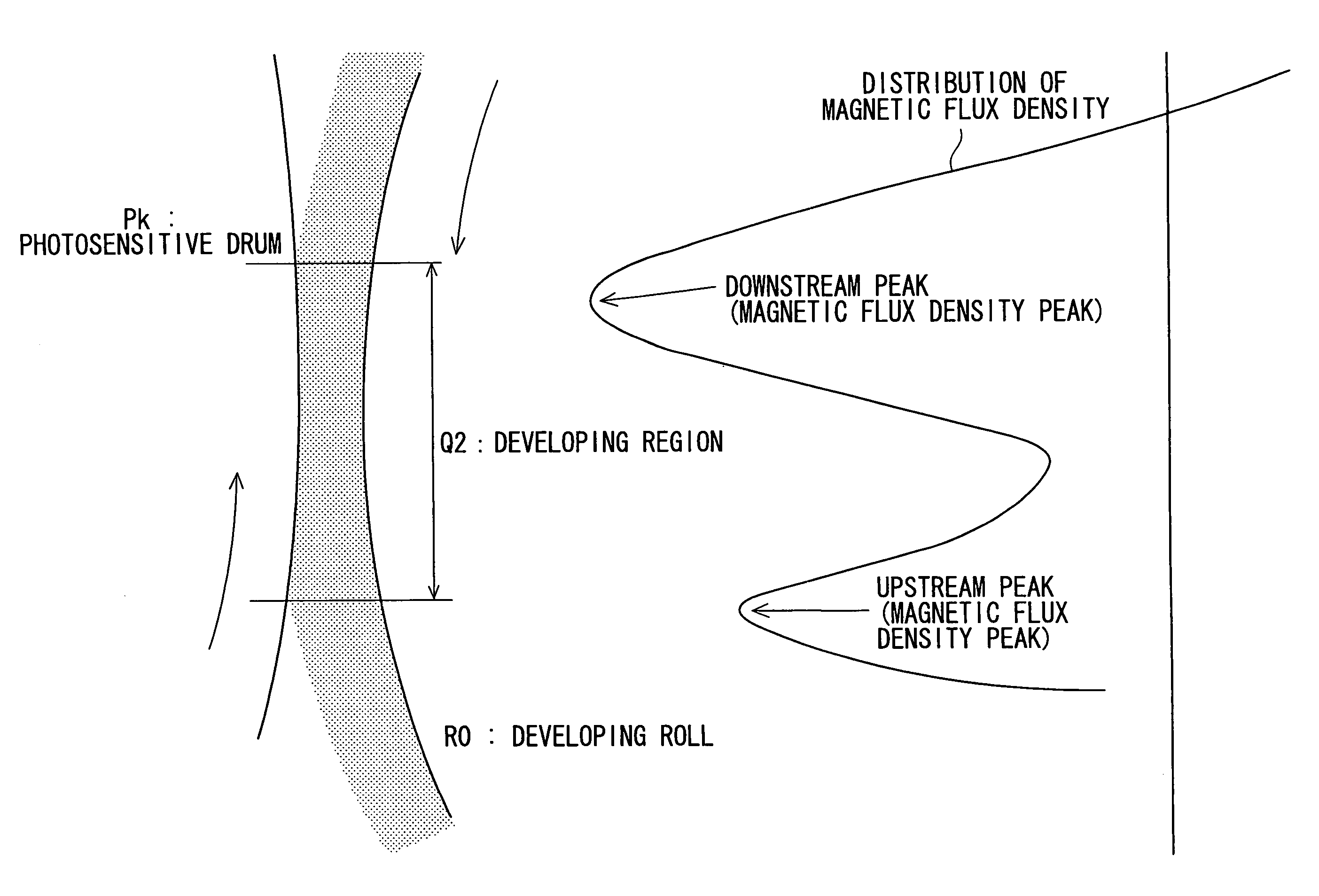
TABLE 2Evaluation results of toner density latitude / carrier adherence to photosensitive drum1.5-μm3.2-μm5.1-μm5.8-μm6.5-μm7.5-μmtonertonertonertonertonertonerComparativeCarrier withOne main developmentC / CC / CC / CC / CC / CC / CExampleparticlepole: 100 mTdiam.20 μmCarrier withOne main developmentC / CC / CC / CC / CC / CC / Cparticlepole: 100 mTdiam.10 μmPresentCarrier withUpstream pole: 70 mTB / BA / BA / BA / BA / BA / BEmbodimentparticleDownstream pole: 70 mTdiam.20 μmCarrier withUpstream pole: 80 mTB / BA / BA / BA / BA / BA / BparticleDownstream pole: 70 mTdiam.20 μmCarrier withUpstream pole: 70 mTB / AA / AA / AA / AA / AA / AparticleDownstream pole: 80 mTdiam.20 μmCarrier withUpstream pole: 70 mTA...

Example

Example 3

[0167]Printing is executed, in accordance with the electrophotography process under conditions according to table 3, and evaluated in the same manner as in Example 1, except that the volume average particle diameter of the carrier is varied (10 μm and 20 μm) and magnetization of the carrier is varied (42 emu / cm3, 52 emu / cm3 and 62 emu / cm3). Here, only examples of the present embodiment are implemented, and AC development with the upstream pole at 70 mT and the downstream pole at 80 mT is applied. The results are shown in table 3.

[0168]TABLE 3Evaluation results of toner density latitude / carrier adherence to photosensitive drum1.5-μm3.2-μm5.1-μm5.8-μm6.5-μm7.5-μmPresent EmbodimenttonertonertonertonertonertonerCarrier with particleUpstream pole: 70 mTA / AA / AA / AA / AA / AA / Adiam 20 μm, magnetizationDownstream pole: 80 mT42 emu / cm3Carrier with particleUpstream pole: 70 mTA / AA / AA / AA / AA / AA / Adiam 20 μm, magnetizationDownstream pole: 80 mT52 emu / cm3Carrier with particleUpstream pole: 70...


PUM


Abstract

A developing device for developing an electrostatic latent image, which is formed on an image-bearing body, with a developer which includes a toner and a carrier, the developing device comprises a developing roll, which includes a fixed magnet at an interior portion and a rotatable sleeve at an outer side thereof, and which is disposed to oppose the image-bearing body, rotates while carrying the developer, and conveys the developer to a developing region in a direction opposite to a direction of progress of the image-bearing body for developing the electrostatic latent image formed on the image-bearing body, wherein the developing roll includes a magnetic pole which includes, in a circumferential direction of the developing roll, at least two magnetic flux density peaks with the same polarity in the developing region, one of the magnetic flux density peaks opposing an end portion of the developing region at a downstream side in the direction of progress of the image-bearing body.

Description

CROSS-REFERENCE TO RELATED APPLICATION[0001]This application claims priority under 35 USC 119 from Japanese Patent Application No. 2004-274154, the disclosure of which is incorporated by reference herein.BACKGROUND OF THE INVENTION[0002]1. Field of the Invention[0003]The present invention relates to a developing device to be employed in an image formation device at which an electrophotography system is applied, such as a copier, a printer, a fax machine, a multifunction device including functions thereof and to an image formation device which employs this developing device.[0004]2. Description of the Related Art[0005]Conventionally, a developing device which is charged with a developing agent (a “two-component developer” formed of a toner and a magnetic carrier) is mounted at an image formation device at which an electrophotography system is applied, such as a copier, a printer, a fax machine, a multifunction device including functions thereof, or the like. This developing device (a...

Claims


Application Information

Patent Timeline
IPC IPC(8): G03G15/09
CPCG03G15/0921G03G2215/0609
Inventor NODA, AKIHIKOMATSUOKA, HIROTAKAKUBO, TSUTOMU
Owner FUJIFILM BUSINESS INNOVATION CORP
Why Eureka
Try Eureka