
Micro-magnetization analysis program, method, and apparatus

Inactive Publication Date: 2007-06-26
FUJITSU LTD
View PDF3 Cites 16 Cited by
  • Summary
  • Abstract
  • Description
  • Claims
  • Application Information

AI Technical Summary

Benefits of technology

[0007]According to the present invention is to provide a micro-magnetization analysis program, method, and apparatus which can analyze transitional change of a micro-magnetization state while one of a plurality of magnetic substances such as a recording medium and a recording head is moved in an arbitrary direction.
[0037]According to the present invention, when the finite element method and the boundary element method are used in equations of the magnetic field with respect to a conventional micro-magnetization analysis method using the finite element method in the equations of magnetic fields and using the finite volume method in the LLG equation describing motion of micro-magnetization, the process of subjecting an air region between models to mesh division and solving magnetic field equations for each minute element becomes unnecessary, and transitional change of a magnetization state can be analyzed while a model such as a magnetic substance is being moved in an arbitrary direction. When micro-magnetization analysis in which a magnetic substance or the like is moved is to be performed by means of a conventional method, a plurality of models in which a model serving as a movement object is shifted little by little has to be generated in advance, and files have to be sequentially read for performing calculation while saving intermediate processes. However, according to the present invention, transitional magnetic change can be continuously analyzed while moving a particular model among a plurality of models in an arbitrary direction, and calculation time for model generation and magnetization analysis can be significantly shortened since a plurality of models corresponding to movement positions is not required to be generated and analyzed. Furthermore, although the type of mesh shape is limited to merely tetrahedrons or hexahedrons in the conventional method in which all the regions including the space between models are solved by the finite element method due to characteristics of the equations of magnetic fields; in the method of the present invention in which the mesh of the space between the models is not required, since tetrahedrons or hexahedrons can be respectively selected for each model region to generate mesh, micro-magnetization analysis for models having complex shapes is facilitated, and calculation accuracy can be enhanced since mesh quality is improved. The above and other objects, features, and advantages of the present invention will become more apparent from the following detailed description with reference to the drawings.

Problems solved by technology

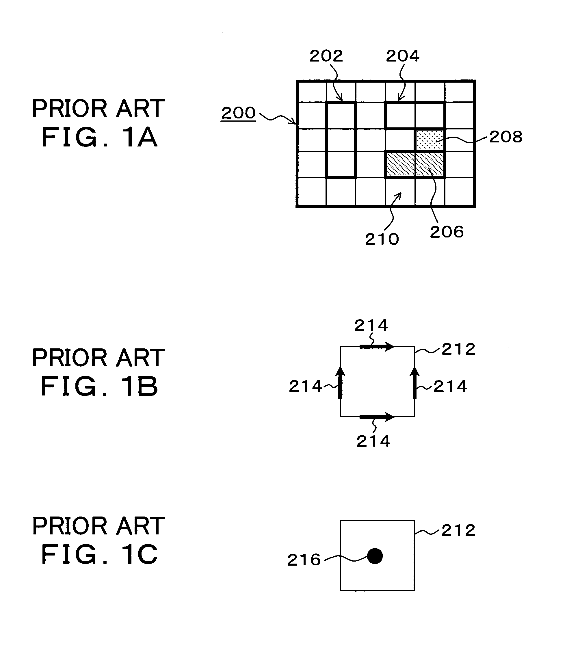
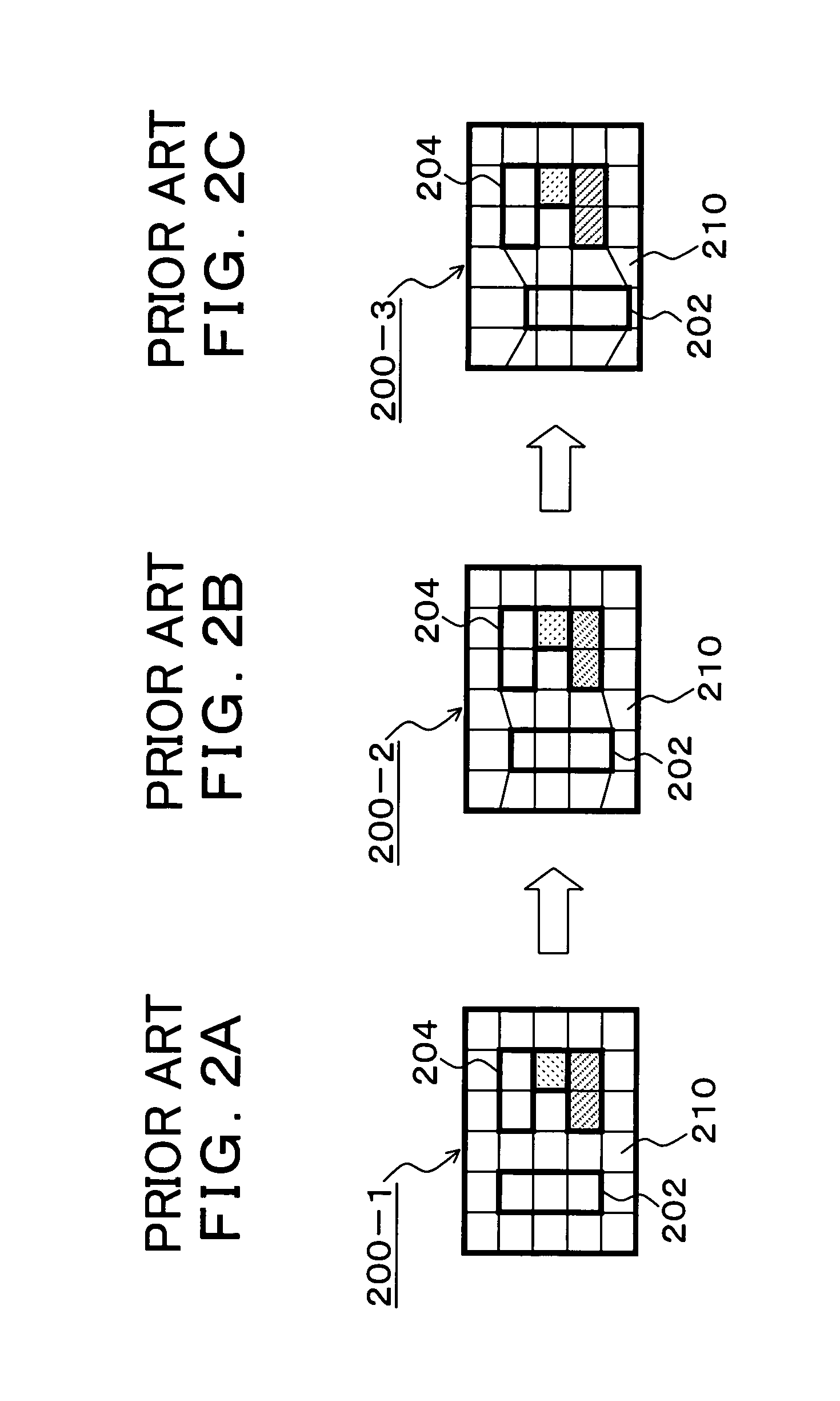
Therefore, minute elements caused by mesh division are present also in the air regions 210 between the magnetic substance regions of the recording medium 202 and the magnetic substance regions constituting the recording head 204, thereby leading to a problem that numerical analysis of the magnetization state during a recording process cannot be performed while the magnetic substance regions of the recording medium 202 are moved.
In addition, when air regions between magnetic substance regions are to be subjected to mesh-division to generate minute elements in the conventional manner, continuity of the minute elements has to be maintained; therefore, it is difficult to generate a magnetic region having a simple shape such as a recording medium as a model in the vicinity of a magnetic substance region having a complex shape such as a recording head.
Furthermore, there is also a problem that, along with movement of the magnetic substance region of the recording medium 202, the mesh shape of the air region 210 between the region and the magnetic substance region of the recording head 204 side is deformed from an initially set rectangle to a trapezoid, and this deformation of the mesh lowers the calculation accuracy.

Method used


Image

  • Micro-magnetization analysis program, method, and apparatus
  • Micro-magnetization analysis program, method, and apparatus
  • Micro-magnetization analysis program, method, and apparatus

Examples


Embodiment Construction

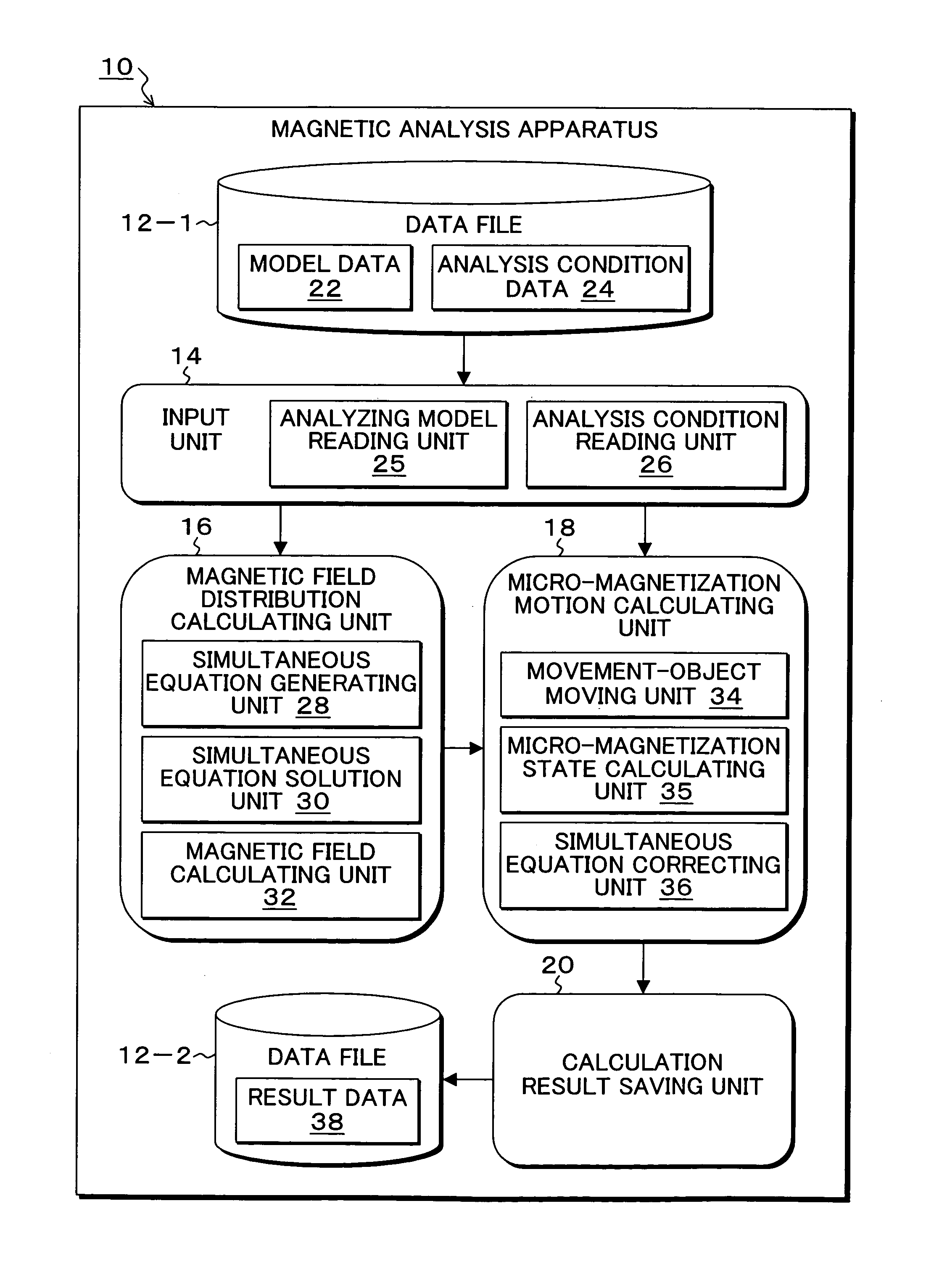
[0054]FIG. 3 is a block diagram of a functional configuration of a magnetic analysis apparatus which executes a micro-magnetization analysis program according to the present invention. In FIG. 3, in a magnetic analysis apparatus 10, a data file 12-1, an input unit 14, a magnetic field calculating unit 16, a micro-magnetization motion calculating unit 18, a calculation result saving unit 20, and a data file 12-2 are provided. Among these, functions of the input unit 14, the magnetic field distribution calculating unit 16, the micro-magnetization motion calculating unit 18, and the calculation result saving unit 20 are functions which are realized by executing the micro-magnetization analysis program of the present invention by a computer. Model data 22 of an analysis object model and analysis condition data 24 which is necessary for micro-magnetization analysis is stored in the data file 12-1. An analyzing model reading unit 25 and an analysis condition reading unit 26 are provided i...


PUM


Abstract

A micro-magnetization analysis program, method, and apparatus which can analyze transitional change of a micro-magnetization state while one of a plurality of magnetic substances such as a recording medium and a recording head is moved in an arbitrary direction. An input unit reads an analysis object model in which merely regions of a magnetic substance fixed in a space and a magnetic substance to be moved are subjected to mesh-division into minute elements and analysis conditions. A magnetic field distribution calculating unit generates a first magnetic field equation, generates a second magnetic field equation, and solves the simultaneous equations thereof.

Description

[0001]This application is a priority based on prior application No. JP 2006-033640, filed Feb. 10, 2006, in Japan.BACKGROUND OF THE INVENTION[0002]1. Field of the Invention[0003]The present invention relates to a micro-magnetization analysis program, method, and apparatus for analyzing a state or change of micro-magnetization of magnetic substances of micron- or nano-order regions; and, particularly relates to a micro-magnetization analysis program, method, and apparatus for analyzing micro-magnetization by using the finite element method and the boundary element method in discretization of two magnetic substances which move relative to each other with respect to, for example, writing or reading of a magnetic head of a hard disk, using the finite volume method in discretization of an LLG equation describing motion of the micro-magnetization, and providing simultaneous equations thereof.[0004]2. Description of the Related Arts[0005]Conventionally, as a micro-magnetization analysis pr...

Claims


Application Information

Patent Timeline
IPC IPC(8): G01R21/06G06F19/00G06F17/50
CPCG01R33/1207
Inventor SHIMIZU, KOICHI
Owner FUJITSU LTD
Learn More