Projectile firing device

a firing device and projectile technology, applied in the direction of firing/trigger mechanism, weapons, launching weapons, etc., can solve the problem of not being able to quickly install small clusters of anti-tank mines, and achieve the effect of quick and accurate installation

Inactive Publication Date: 2007-07-03
NEXTER SYST SA
View PDF17 Cites 12 Cited by
  • Summary
  • Abstract
  • Description
  • Claims
  • Application Information

AI Technical Summary

Benefits of technology

[0012]Thus the firing device according to the invention enables the quick and accurate installation of the projectiles, at a relatively short distance from the carrier vehicle, but in any direction around the vehicle.
[0013]The device according to the invention also enables the selection of the type of projectile to be scattered without the necessity of complicated maneuvers.

Problems solved by technology

Moreover, they are not suited to the rapid installation of small clusters of anti-tank mines, namely used to obstruct a passing place.

Method used


Image

  • Projectile firing device
  • Projectile firing device
  • Projectile firing device

Examples


Embodiment Construction

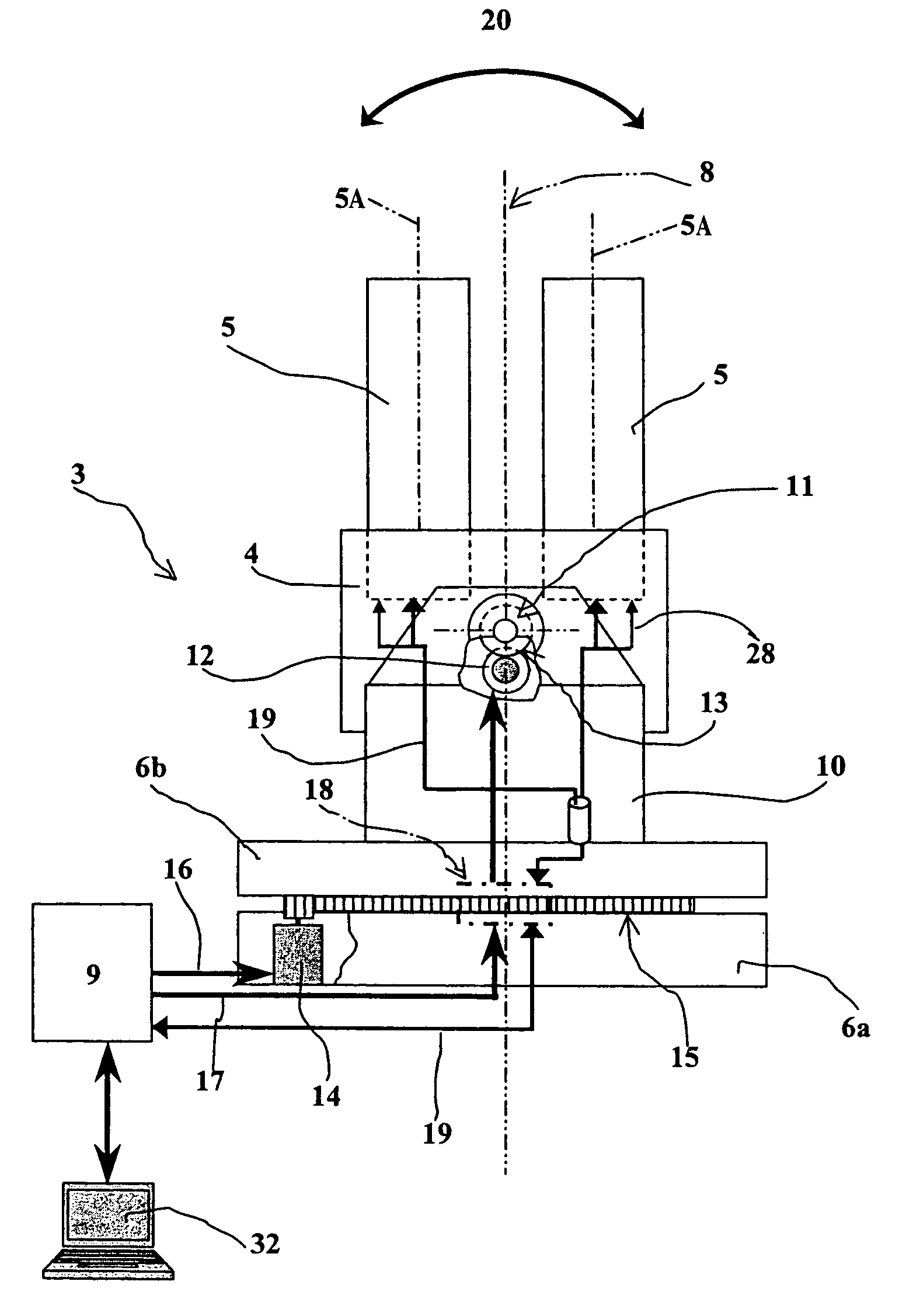
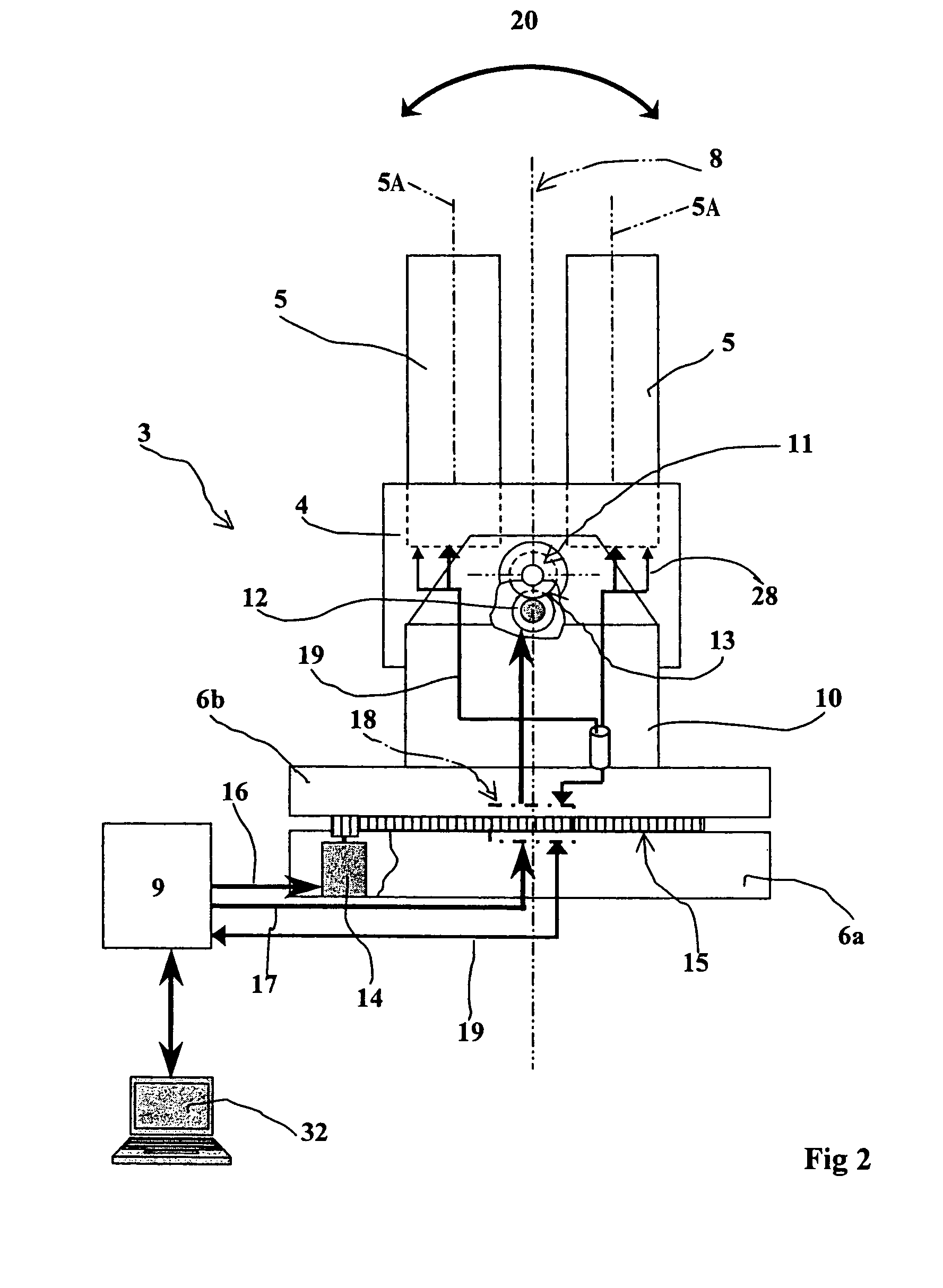
[0028]With reference to FIG. 1, a wheeled armored vehicle 1 incorporates a rear bed 2 onto which is installed a firing device 3 according to the invention.

[0029]This device comprises a base 4 carrying projectile launcher tubes 5 (not shown in this figure), here there are two rows of three tubes 5. Each tube encloses at least one projectile as well as a propellant charge enabling the projectile to be expelled from the tube.

[0030]The projectile may be constituted by a stack of anti-tank mines or by non-lethal ammunition. The tube 5 may advantageously be fastened to the base by a quick assembly method, for example using a bayonet. Such a consumable tube will thus constitute a piece of ammunition that can be replaced after firing. One example of a launcher tube 5 will be described hereafter.

[0031]The base 4 is mounted able to swivel on a turret 6 around a first, substantially horizontal, axis 7.

[0032]The turret 6 itself is able to pivot with respect to the platform 2 around a second axi...


PUM


Abstract

The invention relates to a projectile firing device used on a platform and comprising at least two tubes integral with a base.This device is characterized in that the base is mounted able to swivel on a turret around a first, substantially horizontal axis, such swiveling controlled by first drive means, the turret being able itself to pivot with respect to the platform around a second substantially vertical axis and being controlled by second drive means, the horizontal swiveling being made on either side of a median position in which the tubes are oriented with their axes substantially vertical.

Description

BACKGROUND OF THE INVENTION[0001]1. Field of Invention[0002]The technical scope of the invention is that of devices enabling projectiles to be fired from a platform.[0003]2. Description of Related Art[0004]Known devices comprise one or several tubes integral with a base, each tube being intended to receive at least one projectile as well as a propellant charge enabling said projectile to be expelled.[0005]It is thus known for turrets to be made for cannons, which are mobile in traverse (that is to say around a vertical axis) and in elevation (with respect to a horizontal axis). Cannon turrets are more often than not implemented on armored vehicles and are generally able to swivel in traverse around 360°.[0006]The elevation swiveling capacity is, however, more like 50° at most for a medium-calibre anti-aircraft cannon turret.[0007]It is known to implement multi-tube devices to ensure the scattering of mines. These devices comprise at least two rows of multi-tube bases, able to move o...

Claims


Application Information

Patent Timeline
Patent Type & Authority Patents(United States)
IPC IPC(8): F41F1/06F41A19/68F41A27/08F41A27/28
CPCF41A19/68F41A27/08F41A27/28
Inventor LAINE, LOIC
Owner NEXTER SYST SA
Why Eureka
Try Eureka