Surgical apparatus with indicator

a technology of surgical instruments and indicators, applied in the field of surgical instruments, can solve the problems of poor visual clarity, poor approximation accuracy, and difficulty in determining if proper approximation and/or alignment has been achieved, and the viewing scope may be less than optimal

Inactive Publication Date: 2007-07-03
UNITED STATES SURGICAL CORP
View PDF88 Cites 1481 Cited by
  • Summary
  • Abstract
  • Description
  • Claims
  • Application Information

AI Technical Summary

Benefits of technology

[0009]In another embodiment of the invention, visual indication means are provided which generate a visual indication at a location remote from the surgical instrument to which the visual indication relates. For example, in laparoscopic or endoscopic surgery, surgical instrumentation is utilized such that the surgery may be performed in a minimally invasive manner. In such procedures, the surgeon typically views the movements and actions of the surgical instrumentation on a video monitor positioned in the operating room, the image being delivered to the monitor by cooperating equipment which includes a rigid or flexible endoscope / laparoscope, a light source delivered to the operative site, a camera adapter associated with the endoscope / laparoscope and appropriate transmission cables and the like. According to the present invention, surgical instrumentation to be utilized in the laparoscopic / endoscopic procedure are provided with visual indication means which sense the relative position or condition of the instrument and, through transmission cables and the like, transfer data concerning the position / condition of the instrument to the video monitor. The data is preferably displayed in the form of an icon, symbol or like means, e.g., changes in color, form or position of data displayed on the monitor, which readily communicates to the surgeon relevant information concerning the position / condition of the subject surgical instrumentation.

Problems solved by technology

In performing some surgical procedures, the surgeon may have difficulty in seeing the necessary components to determine when proper approximation has been achieved.
Additionally, even when a surgeon can view the various components being approximated, proper gaps and / or distances may be so minute or precise, that even a trained eye may have difficulty in determining if proper approximation and / or alignment has been achieved.
However, these elements are typically formed in windows in the instruments and require the surgeon to take a close look to obtain the desired information.
If the indicator is positioned on the distal end of the instrument, then the indicator must be configured and colored so that it is readily viewable in the video screen, taking into account that the positioning of the instrument relative to the viewing scope may be less than optimum for viewing the indicator and that the illumination inside the body cavity may be limited.

Method used


Image

  • Surgical apparatus with indicator
  • Surgical apparatus with indicator
  • Surgical apparatus with indicator

Examples


Embodiment Construction

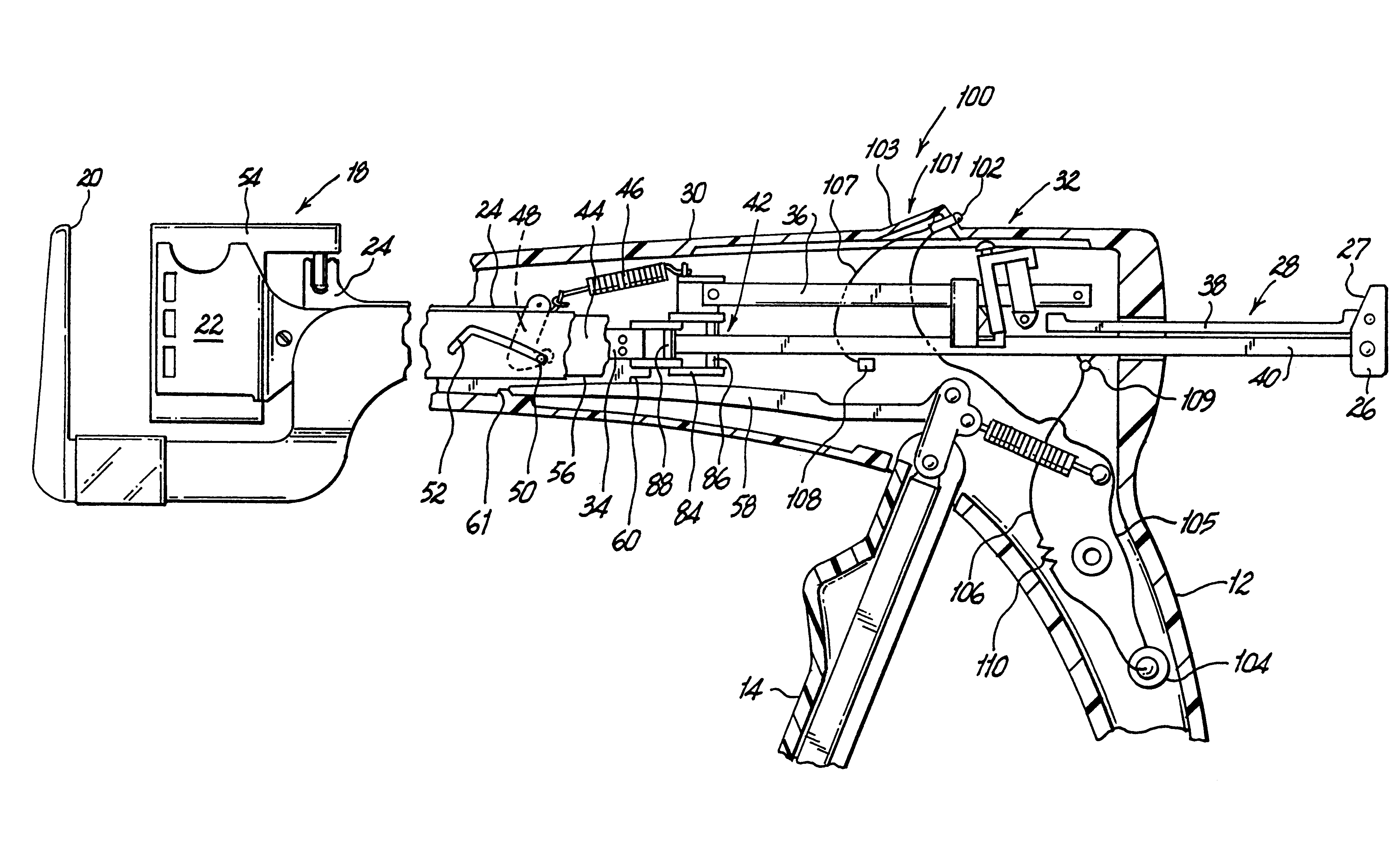
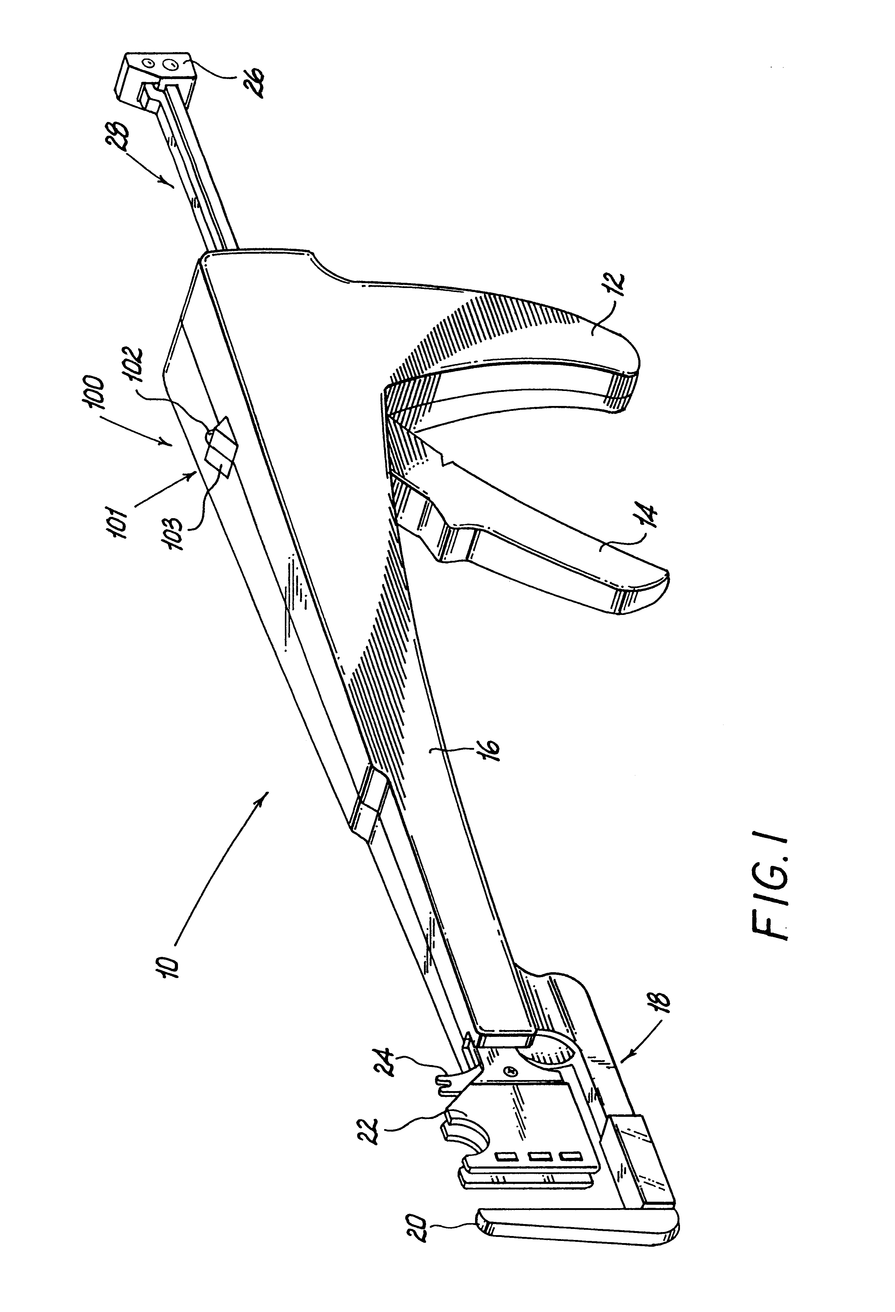
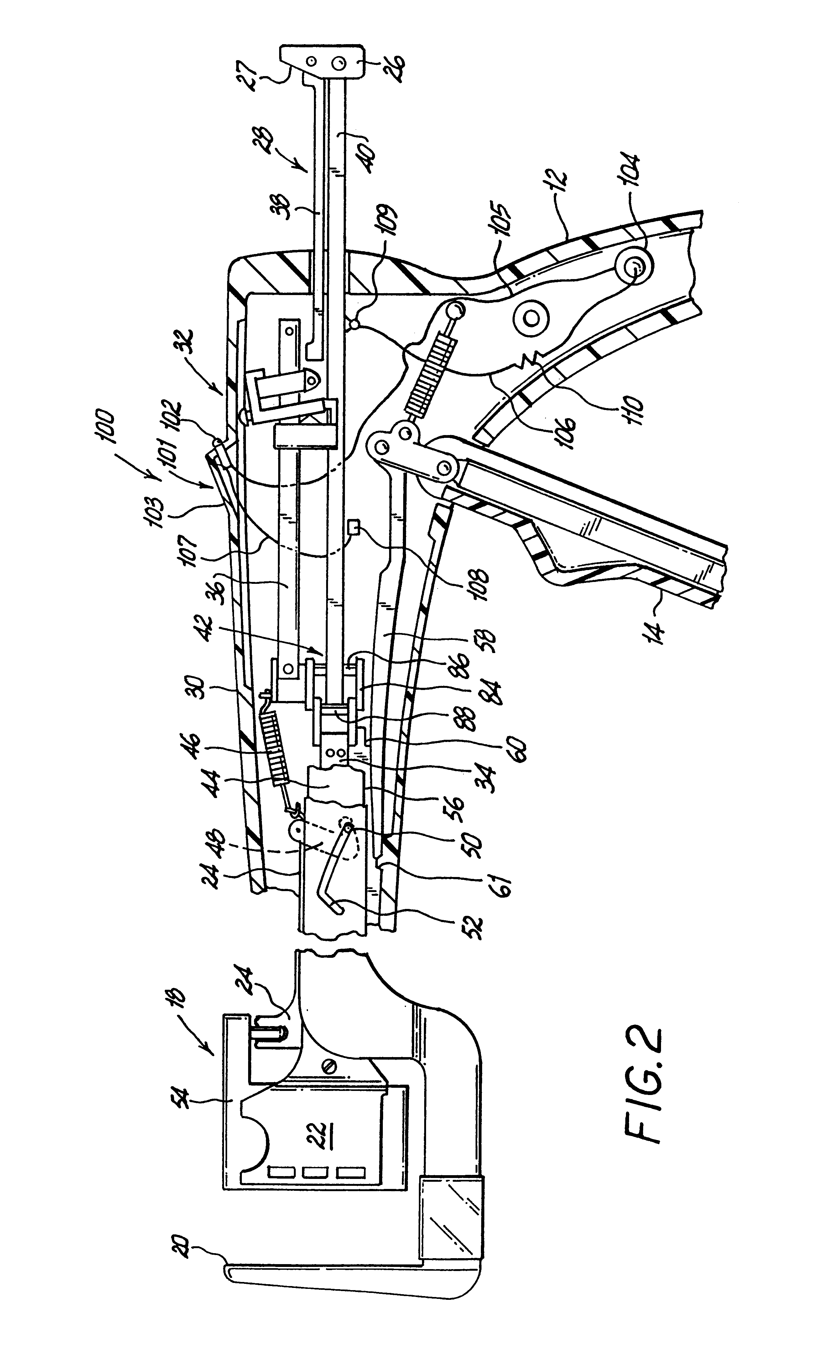
[0023]Referring now in specific detail to the drawings, in which like reference numerals identify similar or identical elements throughout the several views, FIG. 1 shows a surgical fastening instrument 10 which employs an adjustable closure mechanism and the visual indicator device 100 of the present invention. Fastening instrument 10 is provided with a stationary hand grip or hand rest 12 and an actuating handle 14. An elongated body portion 16 is provided which terminates in a distal jaw mechanism 18 which includes an anvil jaw 20 and a cartridge jaw 22. A fastener cartridge (not shown) is positioned within cartridge jaw 22 for driving staples or fasteners through tissue against an anvil surface positioned on anvil jaw 20. Alternatively, the cartridge can contain the fastener portions of two part fasteners which are driven into retainers positioned on the anvil jaw. At the handle end of instrument 10 is provided a push button 26 for operating an advancement mechanism 28, whose fu...


PUM

PropertyMeasurementUnit
distanceaaaaaaaaaa
electricallyaaaaaaaaaa
relative movementaaaaaaaaaa

Abstract

An apparatus and system are disclosed for indicating relative positions of elements in a surgical apparatus. The indicating elements can include electrical circuitry that provides means for activating visual, audible or tactile indicators, thereby alerting the user that an event has occured with respect to the instrument.

Description

[0001]This is a divisional of U.S. application Ser. No. 08 / 109,134 filed Aug. 19, 1993 now U.S. Pat. No. 5,503,320.FIELD OF THE INVENTION[0002]The present invention relates to surgical instruments, e.g., instruments for applying surgical fasteners or staples to body tissue, and more particularly relates to visual indicators for such devices.BACKGROUND OF THE RELATED ART[0003]Surgical fastening or stapling devices have been used in the medical industry for several years. Many of these instruments require approximation of various components during use. When applying surgical fasteners to bodily tissue, for example, various structures of the instrument must be within a predetermined distance in order for the device to properly function. In performing some surgical procedures, the surgeon may have difficulty in seeing the necessary components to determine when proper approximation has been achieved. Additionally, even when a surgeon can view the various components being approximated, pr...

Claims


Application Information

Patent Timeline
Patent Type & Authority Patents(United States)
IPC IPC(8): A61B17/68A61B17/00A61B17/068A61B17/072A61B17/115A61B19/00
CPCA61B17/072A61B17/115A61B17/1155A61B2017/00022A61B2017/00115A61B2017/0725A61B2019/461A61B2090/061
Inventor GUY, THOMAS D.GRANGER, RICHARD N.BRADY, ROBERT H.WEBSTER, JOHNPRATT, JAMES R.STONE, CORBETT W.
Owner UNITED STATES SURGICAL CORP
Why Eureka
Try Eureka