Grinding machine and method of grinding material

a grinding machine and material technology, applied in the field of grinding machines and methods, can solve the problems of limited comminution process effectiveness, inability to increase throughput, and endangered stability of comminution tools fitted to shafts, and achieve the effect of reducing power consumption

Inactive Publication Date: 2007-07-03
METABO LINDEMANN GMBH
View PDF11 Cites 4 Cited by
  • Summary
  • Abstract
  • Description
  • Claims
  • Application Information

AI Technical Summary

Benefits of technology

[0028]the stability of the grinding tools of the shaft is to be increased,
[0031]the power consumption of the machine is to be reduced,
[0047]reducing the power consumptionin order to improve the efficiency of the grinding machine and for the further optimization of the grinding process, use is also made of a controller which obtains its reference variables from at least one gradient of a parameter of the grinding process.

Problems solved by technology

A comminution machine for materials, such as organic waste, bulky waste or the like, assembled in this way in accordance with the prior art described above, in spite of a tried and tested function, still exhibits disadvantages such as:the stability of the comminution tools fitted to the shaft is endangered;the effectiveness of the comminution process is limited by the stationary knives;the throughput cannot be increased, because of the action of the shape of the comminution tools on the shaft, in interplay with the stationary knives, forces material away; andthe power consumption of the machine is relatively high.

Method used


Image

  • Grinding machine and method of grinding material
  • Grinding machine and method of grinding material
  • Grinding machine and method of grinding material

Examples


Embodiment Construction

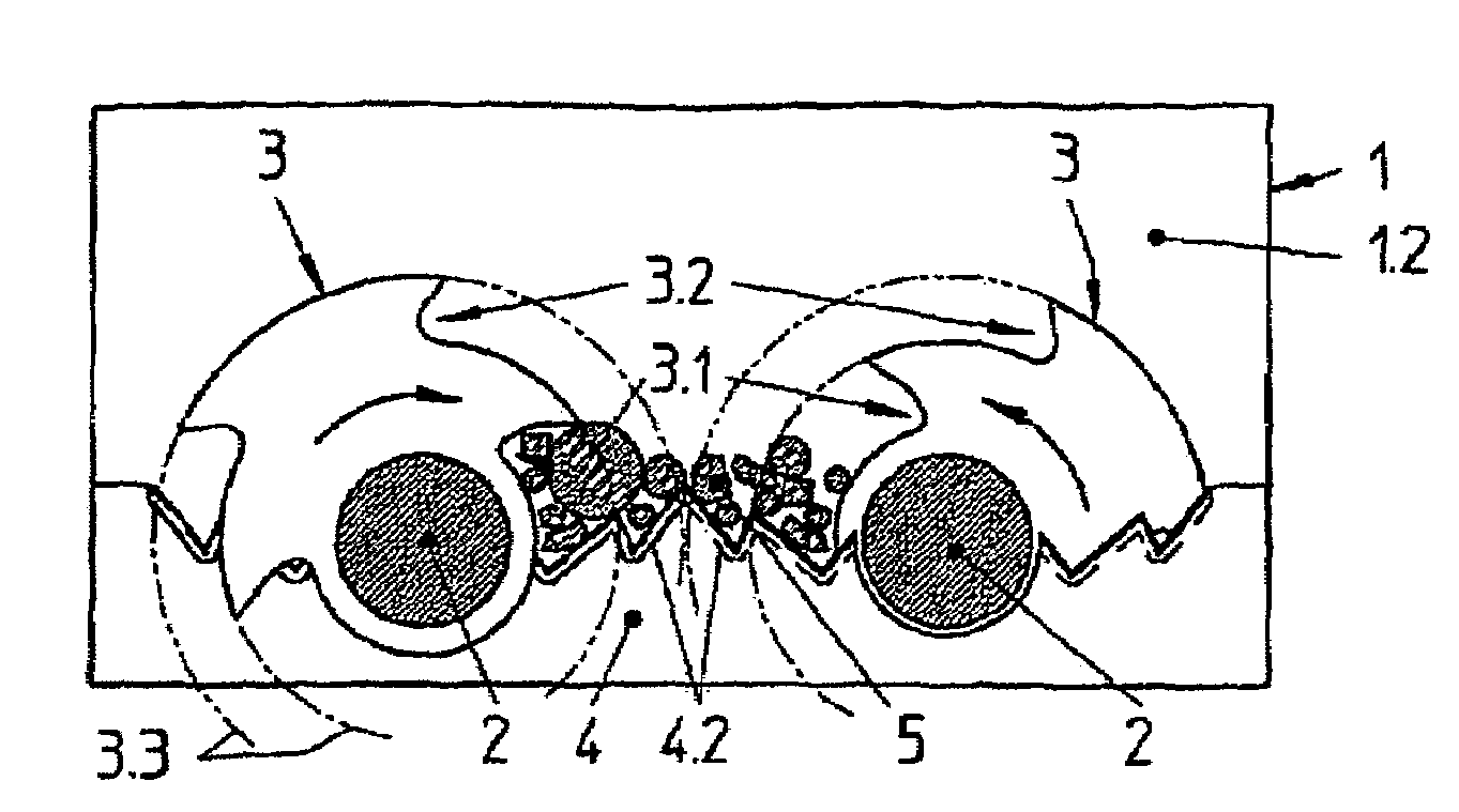
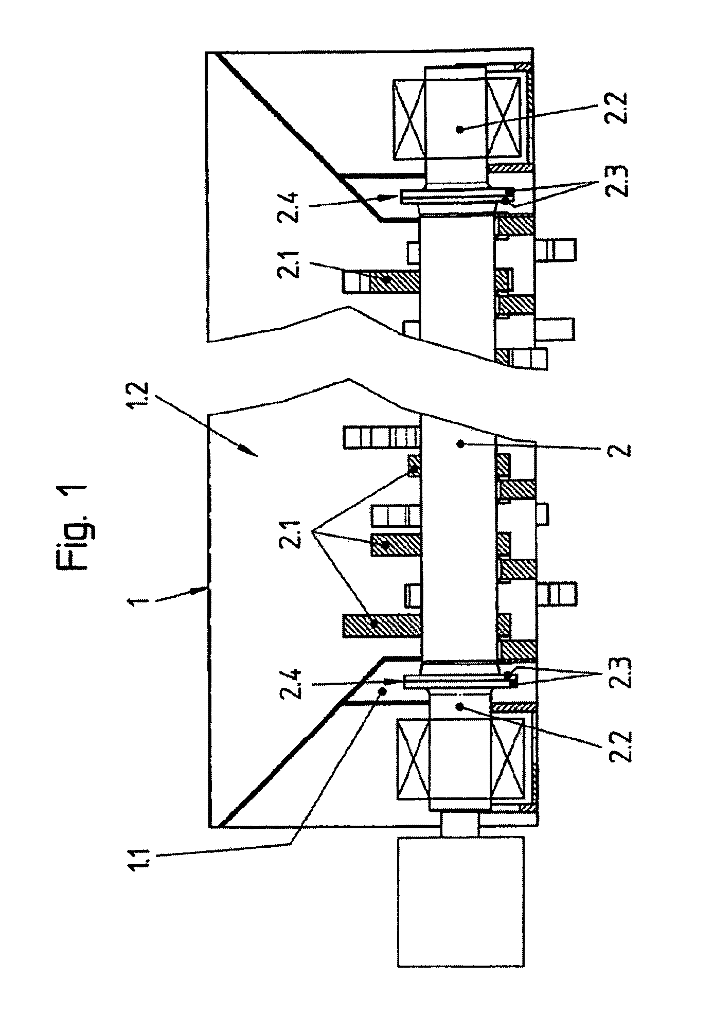
[0054]A grinding machine according to the present invention for domestic waste, bulky waste or wood, according to FIGS. 1 and 2, comprises a housing 1 having two shafts 2 mounted therein and driven in opposite directions. Turning FIG. 2, arranged on the shafts 2 are disks 2.1 which have grinding tools 3. These grinding tools 3 are lined up in a row at intervals from one another on the shafts 2 such that they operate offset in parallel in interaction with rigid cutting tools 4, which run as a slab in the axial direction of the shafts 2, and grind material 5 put in via a receiving element 1.2 in a cutting manner.

[0055]As compared with the known prior art, it is important for the technical requirement on the grinding machine that imaginary extensions of the cutting edges 4.1 (FIGS. 3 to 5) of the rigid cutting tools 4 do not intersect the axis of the shafts 2 or regions around the axis.

[0056]As such, in interplay of the grinding tools 3 with the rigid cutting tools 4, the material 5 ca...


PUM


Abstract

The invention relates to a grinding machine for all kinds of material, the machine comprising: a receiving element for the material (5); at least one shaft (2) positioned in the housing (1) and provided with grinding tools (3); rigid cutting tools (4) which are arranged in the housing (1) and against which the grinding tools (3) operate, grinding the material (5) with specifically low forces. To this end, the grinding tools (3) comprise cutting regions (3.1, 3.2) within which an inner cutting region (3.1) can take a large amount of material (5) to be ground and grind the same, thus comprising a small lever arm, and an outer cutting region (3.2) can take a smaller amount of material (5) to be ground and grind the same, thus comprising a large lever arm. According to the invention, the rigid cutting tools (4) are provided with teeth (4.2) having profiles (4.3) which cooperate with one of the cutting regions (3.1, 3.2), a first transversal edge (3.4) of the grinding tools (3) being oriented towards a second transversal edge (4.4) of a tooth (4.2) of the rigid cutting tools (4) in such a way that it cuts past the same.

Description

CROSS-REFERENCE TO RELATED APPLICATION[0001]This is the National Phase application of PCT / DE2003 / 003375 having an international filing date of 9 Oct. 2003 and which claims priority to German application no. DE10247281.3 filed 10 Oct. 2002, which are herein incorporated by reference.BACKGROUND OF THE INVENTION[0002]The invention relates to a grinding machine and method of grinding for all kinds of material, for example waste, such as domestic waste and bulky waste, or wood. The machines comprises a receiving element for the material, provided in a housing, at least one driven shaft, on which grinding tools are provided, and rigid cutting tools arranged in the housing as opposing tools for the grinding tools for grinding the material.PRIOR ART[0003]Comminution or grinding machines of this type have been disclosed under the designation “Zerreiβer”.[0004]Current grinders such as those disclosed by EP 0 521 081 B1, use the comminution tools that are formed by U-shaped knives, which are l...

Claims


Application Information

Patent Timeline
Patent Type & Authority Patents(United States)
IPC IPC(8): B02C18/16B02C18/14B02C18/18
CPCB02C18/142B02C18/182B02C2018/188
Inventor KOCK, BERNHARD
Owner METABO LINDEMANN GMBH
Why Eureka
Try Eureka