Environmentally stable high resistivity carbon fiber and method of producing

a carbon fiber and high-resistance technology, applied in the field of carbon fiber composition and method of making same, can solve the problems of high cost, manual process of arranging plies, and difficult work with carbon fibers, and achieve the effects of reducing the amount of carbon fiber tows, and controlling electrical resistance levels

Active Publication Date: 2007-07-03
GENERAL ELECTRIC CO
View PDF15 Cites 0 Cited by
  • Summary
  • Abstract
  • Description
  • Claims
  • Application Information

AI Technical Summary

Benefits of technology

[0013]One advantage of the composite construction of the present invention is that it is inexpensive to make.
[0014]Another advantage of the composite construction of the present invention is that it is both elastically complaint while having a wide range of controlled electrical resistance levels.
[0015]An additional advantage of the method for forming composite constructions of the present invention is that it can produce carbon fiber tows having electrical resistance levels that differ by about two orders of magnitude.
[0016]A further advantage of the composite construction of the present invention is that the level of electrical resistance in the carbon fiber tows is substantially constant over a broad range of temperatures and other environmental conditions.

Problems solved by technology

It is extremely difficult to work with carbon fibers at this low concentration level.
Although this construction method has produced promising results, the process of arranging the plies is manual, and hence, is extremely expensive, and impractical for commercial use.
Further, due to the relatively high degree of brittleness, the resulting material simply cannot be handled without breakage.
However, these carbon fibers are produced by attempting to carbonize the carbon fibers at a lower temperature than is used to produce carbon fibers having lower resistance levels.
In fact, at these lower temperatures, the carbon fibers are not fully carbonized, that is, they are not fully converted to carbon, and are believed to retain nitrogen impurities in the fibers.
The carbon fibers produced at the lower carbonizing temperatures by this method are not environmentally stable in that their electrical resistance levels change significantly over time, even at room temperature, and further vary with a change in temperature.
The reason for the fluctuation in resistance of the carbon fibers is believed to be caused by the retained nitrogen which results in an increased propensity of the carbon fibers to accumulate moisture in an unpredictable manner.

Method used


Image

  • Environmentally stable high resistivity carbon fiber and method of producing
  • Environmentally stable high resistivity carbon fiber and method of producing
  • Environmentally stable high resistivity carbon fiber and method of producing

Examples


Embodiment Construction

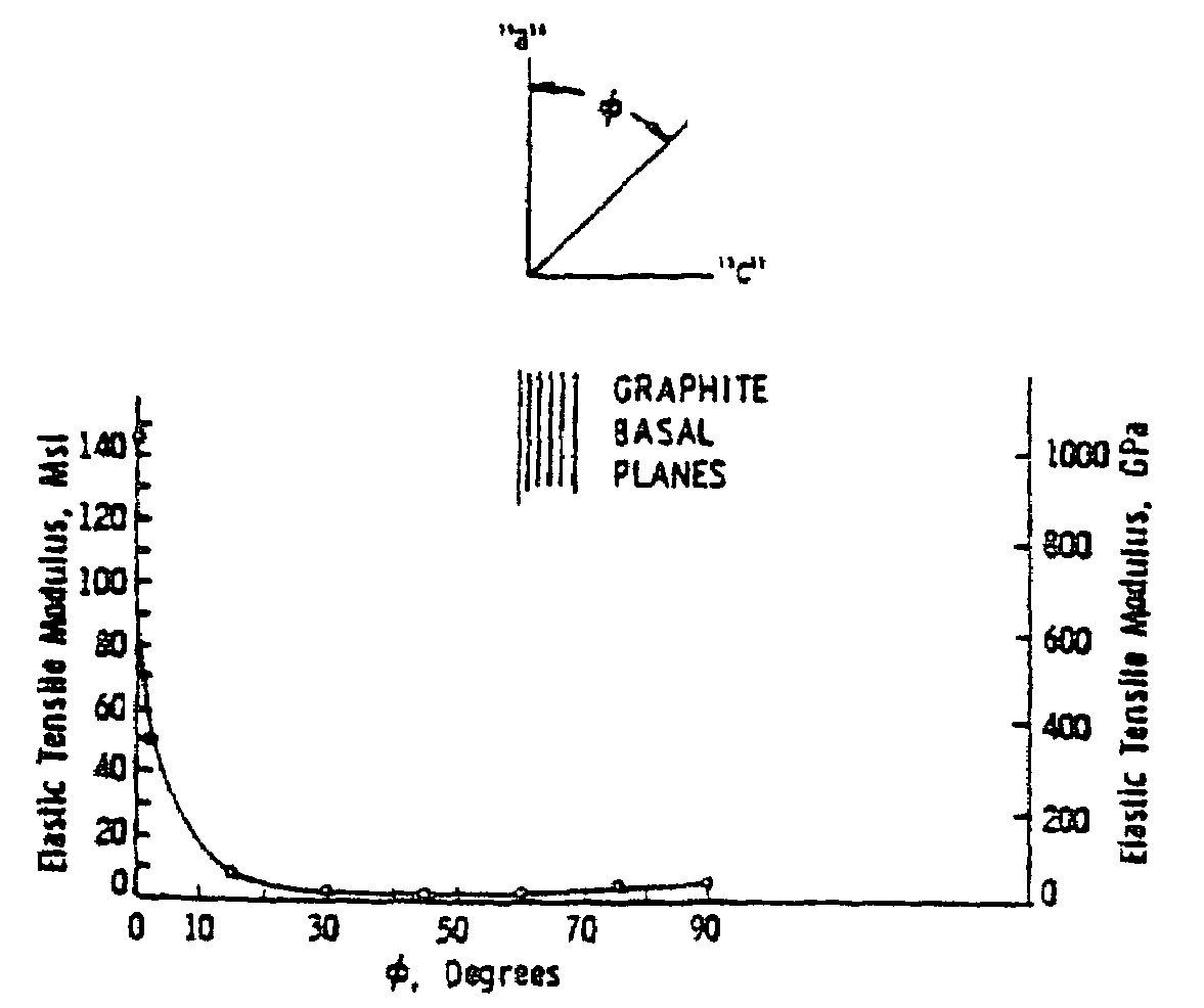
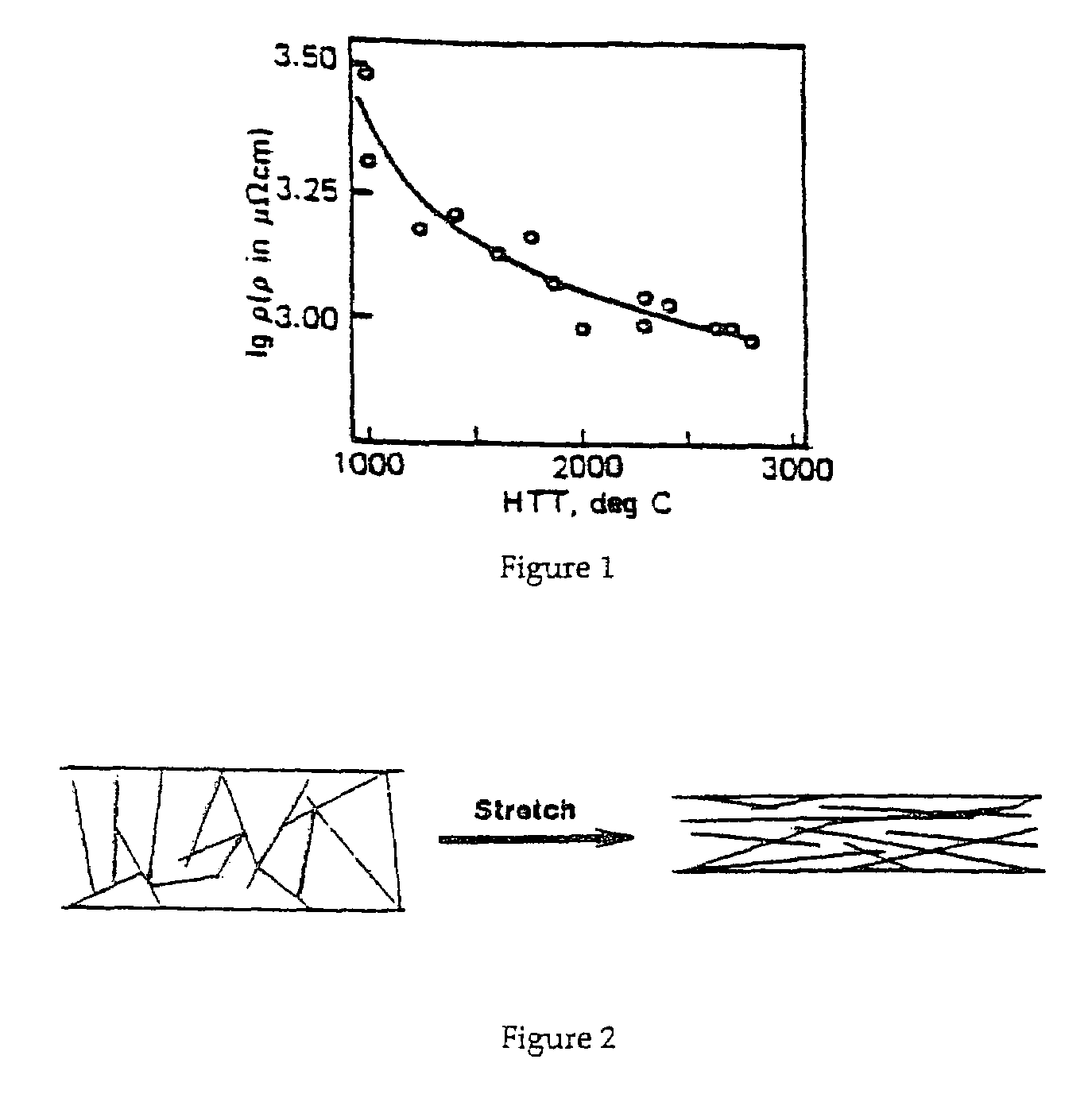
[0024]A typical composite filament construction to which the invention can be applied is illustrated, by means of example, in FIG. 2. As shown, a segment 10 of PAN filaments includes a plurality of carbon PAN molecules 12 disposed in various orientations within filament 10. While it is realized that tows are each comprised of a large number of filaments, such as 1,000 or more, the carbon fibers are generally referred to in their collective construction sense, or tows. As used herein, the term carbon fiber includes precursors from which carbon fibers are produced, such as PAN, rayon and pitch. The orientation of the carbon filaments is expressed in terms of a basal plane that is defined as the plane which is perpendicular to the principal axis in a tow construction. The basal plane is shown in FIG. 5 as a series of horizontal parallel lines, and is also shown perpendicular to axis “c” in a schematic appearing immediately adjacent the basal planes showing axes “a” and “c”, wherein axi...


PUM

PropertyMeasurementUnit
alignment angleaaaaaaaaaa
temperaturesaaaaaaaaaa

Abstract

A carbon composite construction includes carbon fibers having a controlled level of electrical resistance. The controlled level of electrical resistance is achieved by subjecting the carbon fibers to a predetermined stress level during the stabilization process. The carbon fibers produced by this method are blended with nonconductive fibers to produce the composite construction.

Description

BACKGROUND OF THE INVENTION[0001]The present invention relates generally to a carbon fiber composition and method for making same. Specifically, the present invention relates to a carbon fiber composition having a controlled, predetermined electrical resistance level and method for making same.[0002]Composite materials comprising laminated plies of carbon fiber reinforced in a resin matrix are often used due to their high strength to weight ratio. However, in addition to the structural aspects, many applications can greatly benefit from the composite materials having controlled electrical resistance levels. Such applications including engine components, aircraft or land based weapon systems, and heating elements of various kinds, including resistance heating elements, thermal heaters and flexible heating units.[0003]Currently, to make use of carbon fibers in a composite having controlled, lower resistance levels, the amount of carbon fibers must be evenly distributed at extremely lo...

Claims


Application Information

Patent Timeline
Patent Type & Authority Patents(United States)
IPC IPC(8): B32B19/00B32B9/00C01B31/00D01F9/12D04H1/42D04H1/74
CPCD04H1/42D04H1/74Y10T428/2918Y10T428/29Y10T428/2913
Inventor BUCZEK, MATTHEW B.
Owner GENERAL ELECTRIC CO
Why Eureka
Try Eureka