Piezoelectric type vibrator, implantable hearing aid with the same, and method of implanting the same

a technology of piezoelectric and vibrator, which is applied in the field of piezoelectric type vibrator, can solve the problems of not meeting the performance specification required, conventional hearing aid also has a demerit, and a transducer type vibrator, etc., and achieves the effect of simple manufacturing and construction and easy mounting

Active Publication Date: 2007-07-03
KYUNGPOOK NAT UNIV IND ACADEMIC COOP FOUND
View PDF7 Cites 103 Cited by
  • Summary
  • Abstract
  • Description
  • Claims
  • Application Information

AI Technical Summary

Benefits of technology

[0013]Accordingly, the present invention has been made to address and solve the above-mentioned problems occurring in the prior art, and it is an object of the present invention to provide an piezoelectric type vibrator which is implemented in a floating mass type by using a structure which is simply manufactured and constructed, and is easily mounted.
[0015]The piezoelectric element portion of the piezoelectric type vibrator according to the present invention may include one or more piezoelectric elements, and the piezoelectric elements may be connected with one another in series so that maximization of a volume change is caused to thereby maximize a vibration effect.

Problems solved by technology

However, the conventional hearing aid also has a demerit in that it does not satisfy a performance specification required for those who have more than severe hearing loss.
However, the electromagnetic-transducer type vibrator also has a problem in that it is not easy to manufacture since it includes complicated elements such as magnets aligned such that their identical poles are opposed to one another, a coil, a membrane, etc.
However, the conventional piezoelectric type vibrator also has a demerit in that it is difficult to mount.
However, such a conventional piezoelectric type vibrator still has a problem in that its mechanical construction is complicated which is designed for allowing an appropriate pressure to be maintained at the contact portions at the time of mounting one end of the vibrator to the tympanic bone and connecting its other end to the auditory ossicle, as well as allowing an otolaryngologist to easily perform the hearing aid implantation operation in a short time period.

Method used


Image

  • Piezoelectric type vibrator, implantable hearing aid with the same, and method of implanting the same
  • Piezoelectric type vibrator, implantable hearing aid with the same, and method of implanting the same
  • Piezoelectric type vibrator, implantable hearing aid with the same, and method of implanting the same

Examples


first embodiment

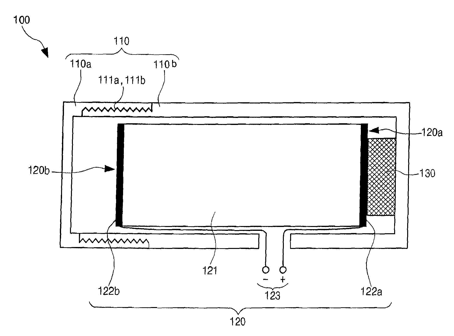
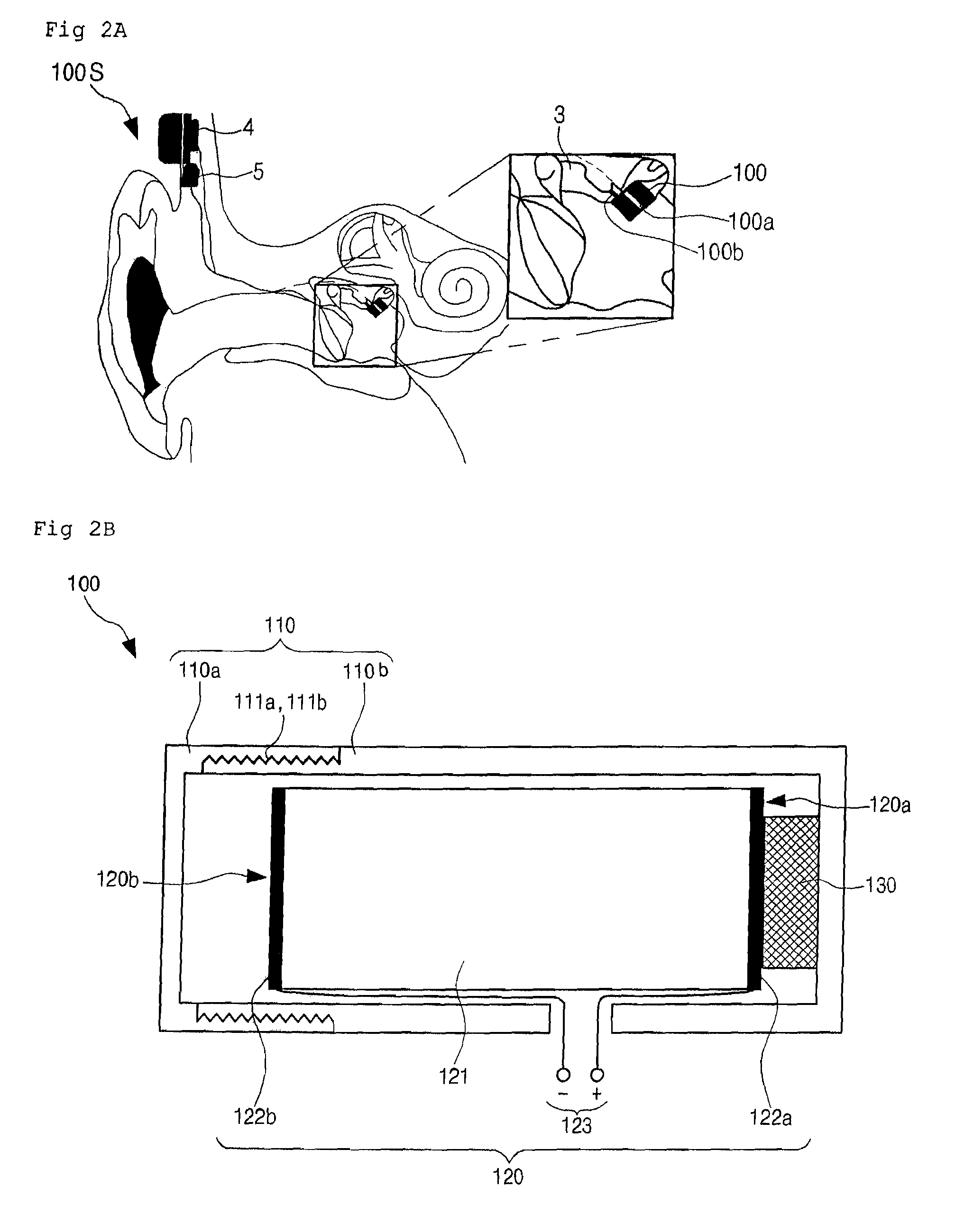
[0039]FIG. 2b is a schematic cross-sectional view illustrating a piezoelectric type vibrator for the implantable middle ear hearing device according to the present invention.

[0040]Referring to FIG. 2b, the piezoelectric type vibrator includes a cylindrical housing 110, a piezoelectric element portion 120 and a connecting portion 130.

[0041]The housing 110 includes a housing cover 110a and a housing body 110b that define an internal space for accommodating the piezoelectric element portion 120 and the connecting portion 130 therein. The coupling portion between the housing cover 110a and the housing body 110b is provided with a male screw part 111a formed on the outer circumferential surface of the housing body 110b and a female screw part 111b formed on the inner circumferential surface of the housing cover 110a. Also, although the housing 110 is configured in a cylindrical shape in which its longitudinal axis corresponds to an axis parallel with a direction where the piezoelectric e...

third embodiment

[0064]In the meantime, in the present invention, in order for the piezoelectric element to more accurately transmit an acoustic vibration signal output therefrom to the auditory ossicle, the connection portion for connecting the piezoelectric element and the housing to each other may take a structure as shown in FIG. 5.

[0065]The connection portion 130″ includes a contact part 131″, a support part 132″ and a mounting part 133″. The contact part 131″ is formed in a coin shape, and is attached at one side thereof to a non-free end of the piezoelectric element portion 120′ (see FIG. 6A) and is attached at the other side thereof to the support part 132″. The support part 132″ is formed in a wheel shape and includes a hub 132″a positioned at the center thereof, an outer rim 132″c concentric with the hub 132″a, and a plurality of spokes 132″b arranged radially around the hub in such a fashion that opposite ends of each spoke 132″b are secured to the hub 132″a and the rim 132″c, respectivel...

fourth embodiment

[0072]FIG. 7a is a is a schematic perspective view illustrating a piezoelectric type vibrator for the implantable hearing device according to the present invention and FIG. 7b is a schematic cross-sectional view taken along the line II-II of FIG. 7a.

[0073]As shown in FIGS. 7a and 7b, a piezoelectric type vibrator 100 according to a fourth embodiment of the present invention includes a housing 110′, a piezoelectric element portion 120′ and a connection portion 130. Here, the piezoelectric element portion and the connection portion according to each of the aforementioned embodiments can be used for the piezoelectric element portion 120′ and the connection portion 130. The detailed description of the piezoelectric element portion, the connection portion as well as the controller 5 and the microphone 4 connected with the piezoelectric type vibrator 100 will be omitted. In addition, the piezoelectric type vibrator 100 has been described, focusing on the connection portion 130 in order t...


PUM


Abstract

Disclosed herein is a piezoelectric type vibrator included in an implantable hearing device. The piezoelectric type vibrator comprises: a housing; a piezoelectric element portion formed at one end thereof with a free end and at the other end thereof with a non-free end, the piezoelectric element portion being at least partially disposed at the inside of the housing and including at least one piezoelectric element and terminals connected to both ends of the piezoelectric element; and a connection portion attached at one end thereof to one side of the inner wall of the housing and at the other end thereof to a non-free end of the piezoelectric element portion.

Description

CROSS-REFERENCES TO RELATED APPLICATIONS[0001]This nonprovisional application claims priority under 35 U.S.C. § 119(a) on Patent Application No. 10-2004-086161 filed in Korea on Oct. 27, 2004, which are hereby incorporated in its entirety by reference.BACKGROUND OF THE INVENTION[0002]1. Field of the Invention[0003]The present invention relates to a piezoelectric type vibrator, and more particularly to a floating mass-type piezoelectric vibrator having a simple structure, an implantable hearing aid having the same, and a method of implanting the hearing aid.[0004]2. Background of the Related Art[0005]A hearing aid can be classified into a conventional body-worn hearing aid and an implantable hearing aid. The conventional hearing aid has a merit in that it can be easily mounted at an auricle and / or an acoustic pore of an external ear. However, the conventional hearing aid also has a demerit in that it does not satisfy a performance specification required for those who have more than s...

Claims


Application Information

Patent Timeline
Patent Type & Authority Patents(United States)
IPC IPC(8): H01L41/053
CPCH04R25/606A61N1/36032B06B1/06G10K9/122
Inventor CHO, JIN-HO
Owner KYUNGPOOK NAT UNIV IND ACADEMIC COOP FOUND
Why Eureka
Try Eureka