Wiring structure of vehicle-mounted antenna system

a technology of wiring structure and vehicle, which is applied in the direction of antenna details, antenna adaptation in movable bodies, antennas, etc., can solve the problems of low reliability of the antenna system, increased signal attenuation, and difficult maintenance, so as to achieve the effect of reducing the cost of the housing, and ensuring the safety of the user

Inactive Publication Date: 2007-07-03
ALPS ALPINE CO LTD
View PDF3 Cites 0 Cited by
  • Summary
  • Abstract
  • Description
  • Claims
  • Application Information

AI Technical Summary

Benefits of technology

[0009]The present invention has been made in view of the problems inherent in the conventional antenna system, and it is an object of the present invention to provide a wiring structure which enhances the reliability of a vehicle-mounted antenna system mounted on the inner surface of a window glass which faces the interior of a vehicle, thereby easily performing maintenance as well.
[0011]If the holding piece is provided in the base plate to be fixed to the glass plate as such, since the feeder line having one end connected to the feeding point of the radiating conductor is inserted between the holding piece and the glass plate and the position is regulated, the feeder line can be efficiently led along a desired path, thereby enhancing the reliability of the antenna system. Further, since an attachment structure can be employed in which the housing having the circuit board accommodated therein is fixed by screws to the base plate which has been fixed to the glass plate in advance, the complex removal work or attachment work during checking or replacement of the circuit board need not be performed, so that the maintenance becomes easy.
[0013]In the above-described wiring structure of the vehicle-mounted antenna system, preferably, the housing includes a frame made of sheet metal which surrounds the circuit board and hold the circuit board, and is detachably fixed to the base plate, and a cover which is made of sheet metal and is crowned on the frame so as to cover the circuit board. With this construction, the cost of the housing can be easily reduced and the circuit board can be simply assembled into the frame before being crowned with the cover. In this case, if a peripheral portion of the cover is provided with a bent piece which fits on the frame, and a portion of the bent piece is provided with a holding groove for positioning a portion in proximity of the other end of the feeder line, the cover can be crowned on the frame with a sufficient large attachment strength without causing any problems to the leading of the feeder line.
[0014]In the above-described wiring structure of the vehicle-mounted antenna system, preferably, the other end of the feeder line is connected to the circuit board by a connector. With this construction, since connection of the feeder line to the circuit board or disconnection of the feeder line from the circuit board can be simply performed, working efficiency greatly improves during working or maintenance of the antenna system.
[0015]According to the present invention, in the wiring structure of a vehicle-mounted antenna system to be mounted on the inner surface of a window glass which faces the interior of a vehicle, the base plate to be fixed to the glass plate is provided with a holding piece, and the position can be regulated by inserting the feeder line between the holding piece and the glass plate. Therefore, the feeder line can be efficiently led along a predetermined path. Further, since an attachment structure can be employed in which the housing having the circuit board accommodated therein is fixed by screws to the base plate which has been fixed to the glass plate in advance, a complex removal work or attachment work during checking or replacement of the circuit board need not be performed, so that the reliability of vehicle-mounted antenna system can be improved and the maintenance thereof can be easily performed.

Problems solved by technology

Since this antenna system is easily subjected to the influence of extraneous noises, there is a problem in that the reliability of the antenna system is lowered.
However, another problem occurs in which the attenuation of signals may increase if the feeder line connected to the feeding point of the radiating conductor is not efficiently led along a predetermined path.
As in the conventional example, in the case of an antenna system in which the electronic circuit unit as an integral part is fixed to the glass plate by soldering or the like, there is also a problem in that maintenance is not easy because of the complexity for removing the electronic circuit unit from the glass plate or attaching it thereto.

Method used


Image

  • Wiring structure of vehicle-mounted antenna system
  • Wiring structure of vehicle-mounted antenna system
  • Wiring structure of vehicle-mounted antenna system

Examples


Embodiment Construction

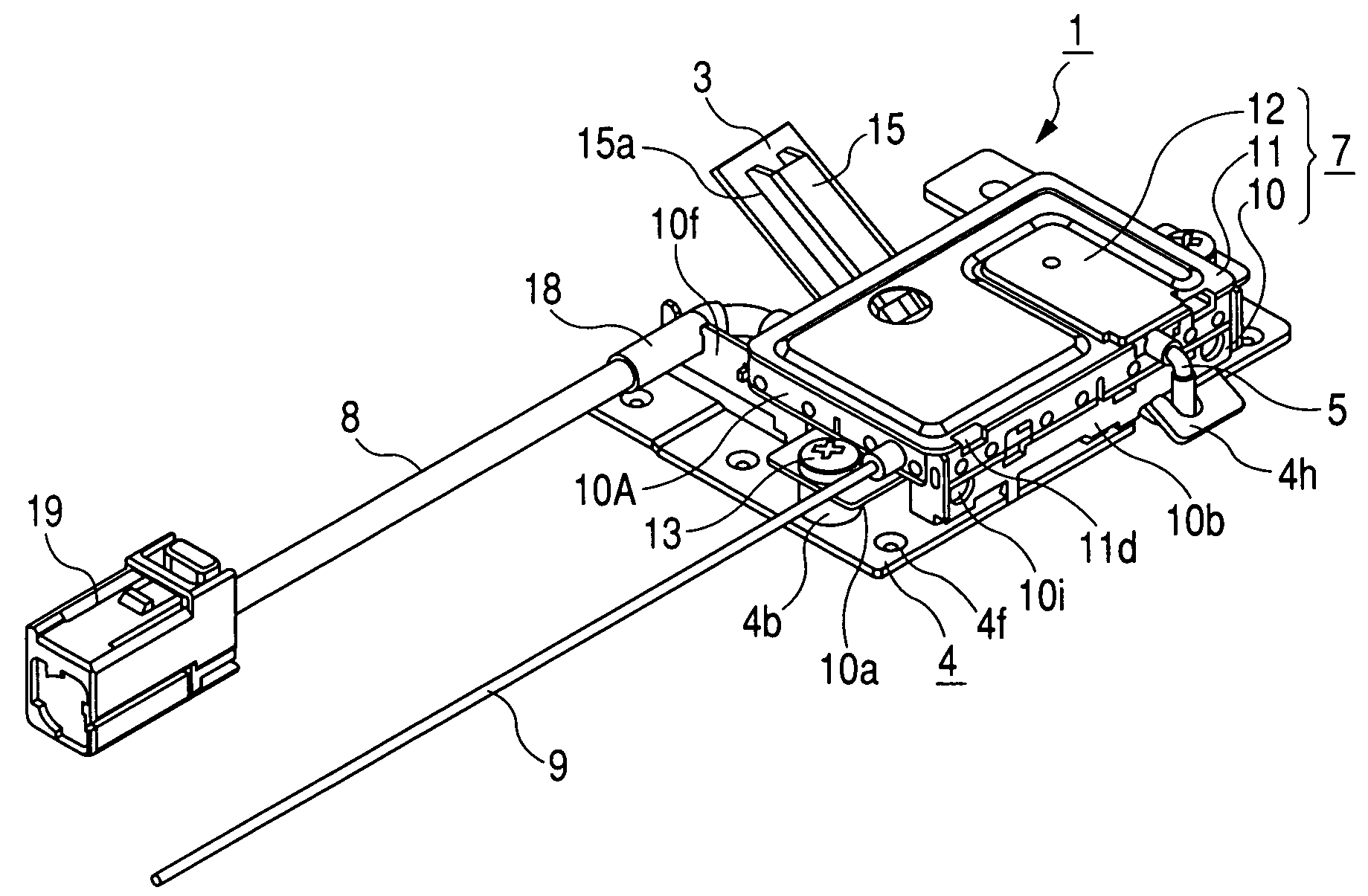
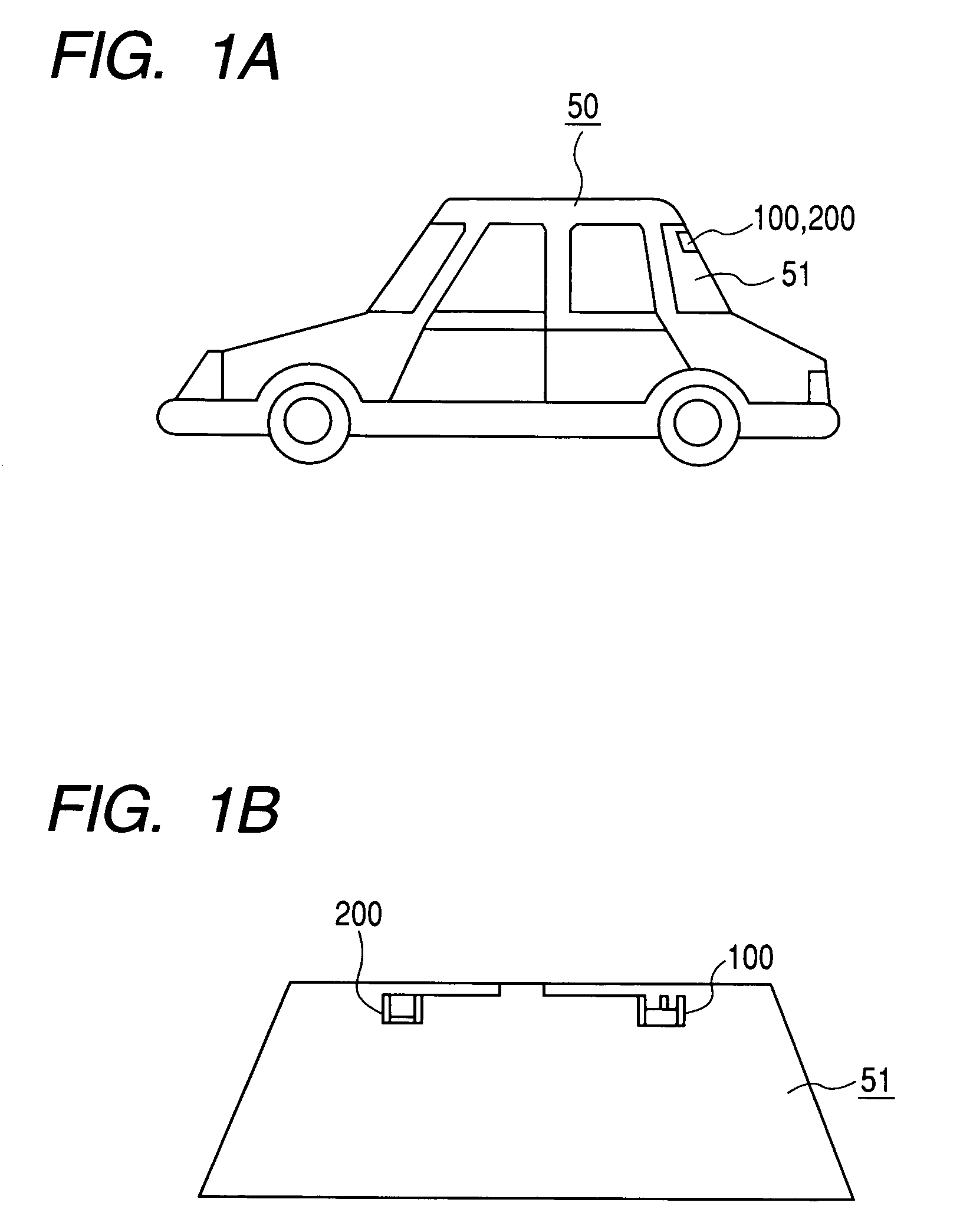
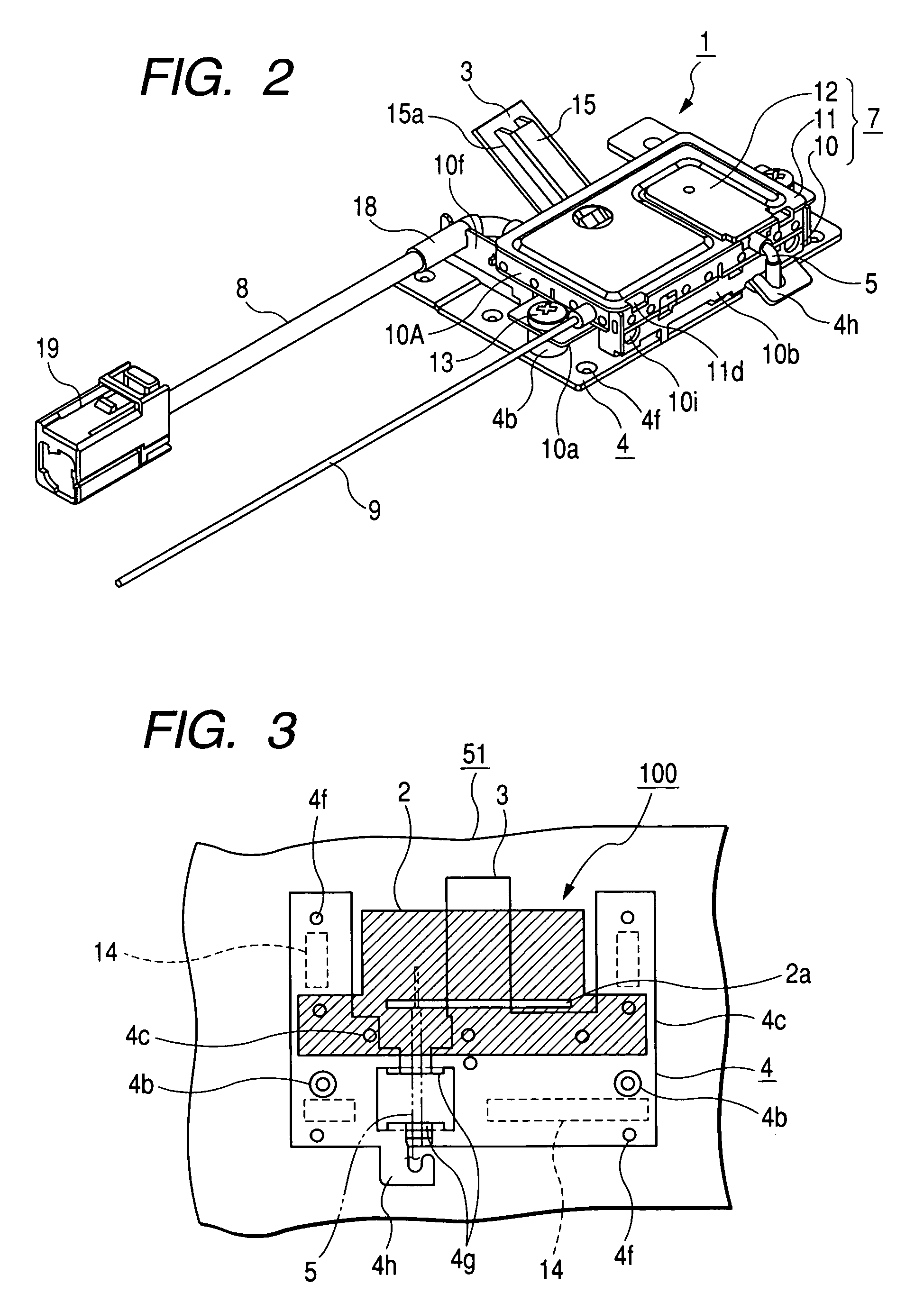
[0031]Preferred embodiments of the present invention will now be described with reference to the drawings. FIG. 1 is an explanatory view showing a mounting position of a vehicle-mounted antenna system according to embodiments of the present invention, wherein FIG. 1A is a side view of a vehicle, and FIG. 1B is a front view of a rear glass as seen from the interior of the vehicle. Further, FIGS. 2 to 8 show a ground-based station antenna device constituting the vehicle-mounted antenna system, wherein FIG. 2 is a perspective view showing an electronic circuit unit of the ground-based station antenna device; FIG. 3 is an explanatory view showing the positional relationship between a base plate and a radiating conductor; FIG. 4 is an exploded perspective view of the electronic circuit unit; FIG. 5 is a plan view of the electronic circuit unit; FIG. 6 is a bottom view of the electronic circuit unit; FIG. 7 is a side view of the electronic circuit unit; and FIG. 8 is a side view of the el...


PUM


Abstract

A glass plate is formed with a radiating conductor. An electronic circuit unit includes a base plate soldered to the radiating conductor to be fixed to the glass plate, a frame fixed to the base plate with screws for accommodating the circuit board, and a cover crowned on the frame. The base plate is provided with a holding piece which protrudes the inside of the frame, and a hooking piece which protrudes out of frame. The cover is provided with a holding groove. A feeder line connected to the radiating conductor is inserted between the holding piece and the glass plate. The feeder line drawn out of the frame is hooked on the hooking piece, and led to the circuit board by the holding groove.

Description

BACKGROUND OF THE INVENTION[0001]1. Field of the Invention[0002]The present invention relates to a vehicle-mounted antenna system to be mounted on the inside of a window glass of a vehicle or the like, and in particular, to a wiring structure of a feeder line which electrically connects a radiating conductor formed on an inner surface of a glass plate with a circuit board accommodated in a housing.[0003]2. Description of the Related Art[0004]Conventionally, there is known a vehicle-mounted antenna system in which a radiating conductor is formed on an inner surface of a rear glass or a front glass of a vehicle which faces the interior of the vehicle and an electronic circuit unit including a pre-amplifying circuit is attached to the inner surface, thereby allowing reception of circularly polarized waves, linearly polarized waves or the like transmitted from satellites or ground-based stations. This type of antenna system has advantages that the service life of the system can be exten...

Claims


Application Information

Patent Timeline
Patent Type & Authority Patents(United States)
IPC IPC(8): H01Q1/32H01Q9/04
CPCH01Q1/325H01Q9/0407
Inventor IKEDA, TOMOKIOSHIMA, HIDEAKIUEDA, MAKOTO
Owner ALPS ALPINE CO LTD
Why Eureka
Try Eureka