Magnetic disk device and electronic apparatus for mounting the magnetic disk device thereto

a magnetic disk and electronic equipment technology, applied in the direction of casings/cabinets/drawers, instruments, casings/cabinets/drawers details of electric apparatus, etc., can solve the problems of increasing the error rate of recording operation and reproducing operation, increasing the error rate of data recorded on the hard disk and data reproduced from the hard disk, etc., to prevent the effect of dampener adversely affecting the magnetic disk devi

Inactive Publication Date: 2007-07-03
ALPINE ELECTRONICS INC
View PDF8 Cites 22 Cited by
  • Summary
  • Abstract
  • Description
  • Claims
  • Application Information

AI Technical Summary

Benefits of technology

[0015]Accordingly, it is a first object of the present invention to provide a magnetic disk device that sufficiently protects a hard disk and a magnetic head unit in a case from, for example, external shock when the magnetic disk device is not mounted to the body of an apparatus, and to prevent a dampener from adversely affecting the magnetic disk device when the magnetic disk device is mounted to the body of the apparatus. A second object of the present invention is to provide an electronic apparatus for mounting the magnetic disk device thereto.
[0018]When the magnetic disk device is removed from the body of the apparatus, the driving unit is set in an elastically supported state in the case by externally operating the locking member, thereby protecting the magnetic disk device from external shock. Immediately before mounting the magnetic disk device to the body of the apparatus or after mounting it to the body of the apparatus, the driving unit is locked in the case by operating the locking member in order to restrict unnecessary movement of the hard disk and the magnetic head unit when performing a recording operation or a reproducing operation, thereby making it possible to reduce error rate.
[0021]By virtue of such a structure, it is possible to move the locking member to the lock position by making use of mounting force is produced when the magnetic disk device is mounted.

Problems solved by technology

In the removable magnetic disk device, the use of a soft elastic member having a low elastic modulus is used as the dampener for protecting the rotary driver and the magnetic head unit in the case may increase the error rate of the recording operation and that of the reproducing operation.
Therefore, when the rotary driver and the magnetic head unit are supported by a soft elastic member in the case, the hard disk and the magnetic head unit tend to move due to vibration generated when the magnetic head unit performs the aforementioned searching operation.
As a result, the error rates of data recorded on the hard disk and of data reproduced from the hard disk are increased.
However, such a hard dampener cannot sufficiently protect the components in the case.
As a result, a large shock applied to the magnetic disk device when, for example, it is dropped by mistake tends to result in, for example, scratching of a surface of the hard disk or damage to the magnetic head chip.

Method used


Image

  • Magnetic disk device and electronic apparatus for mounting the magnetic disk device thereto
  • Magnetic disk device and electronic apparatus for mounting the magnetic disk device thereto
  • Magnetic disk device and electronic apparatus for mounting the magnetic disk device thereto

Examples


Embodiment Construction

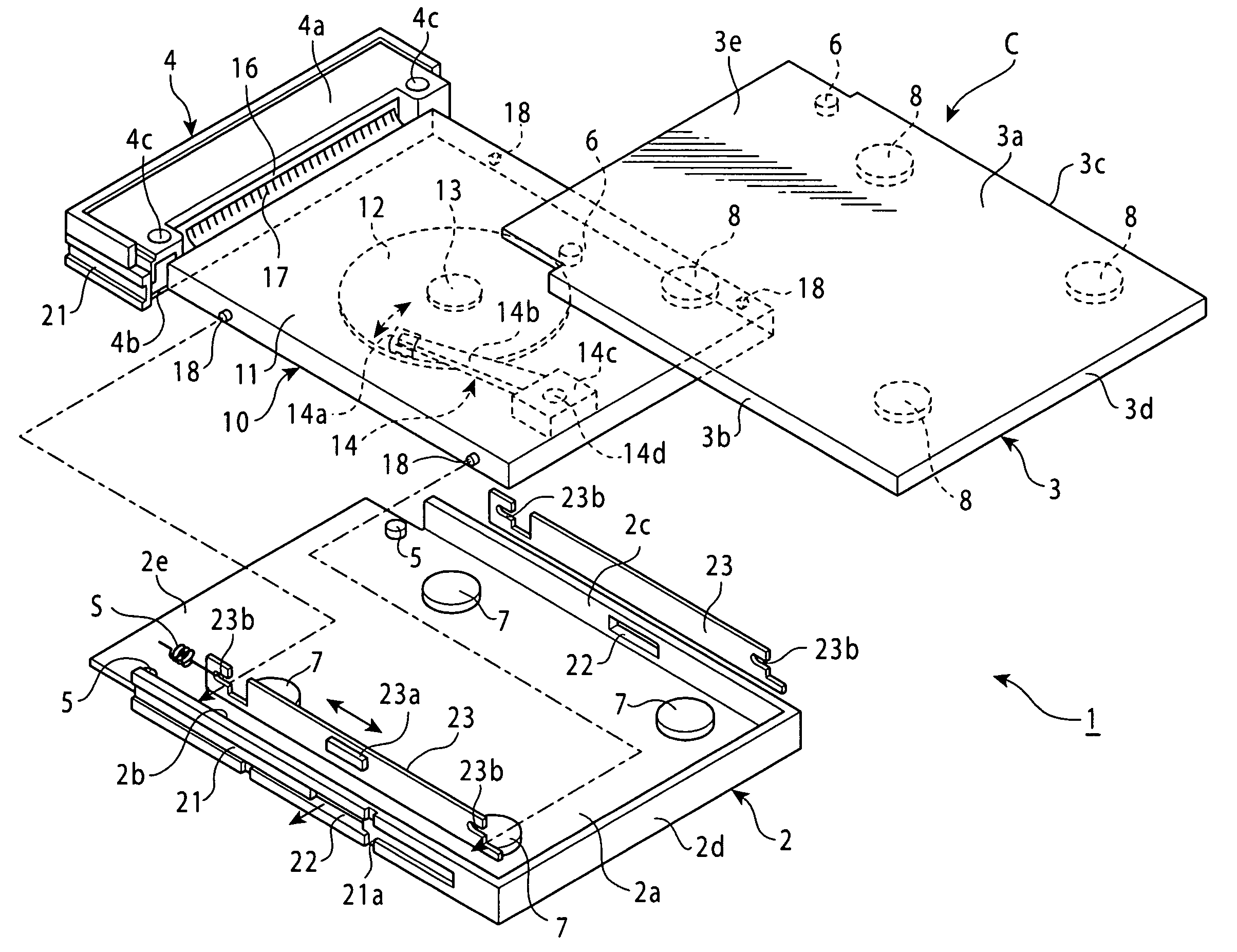
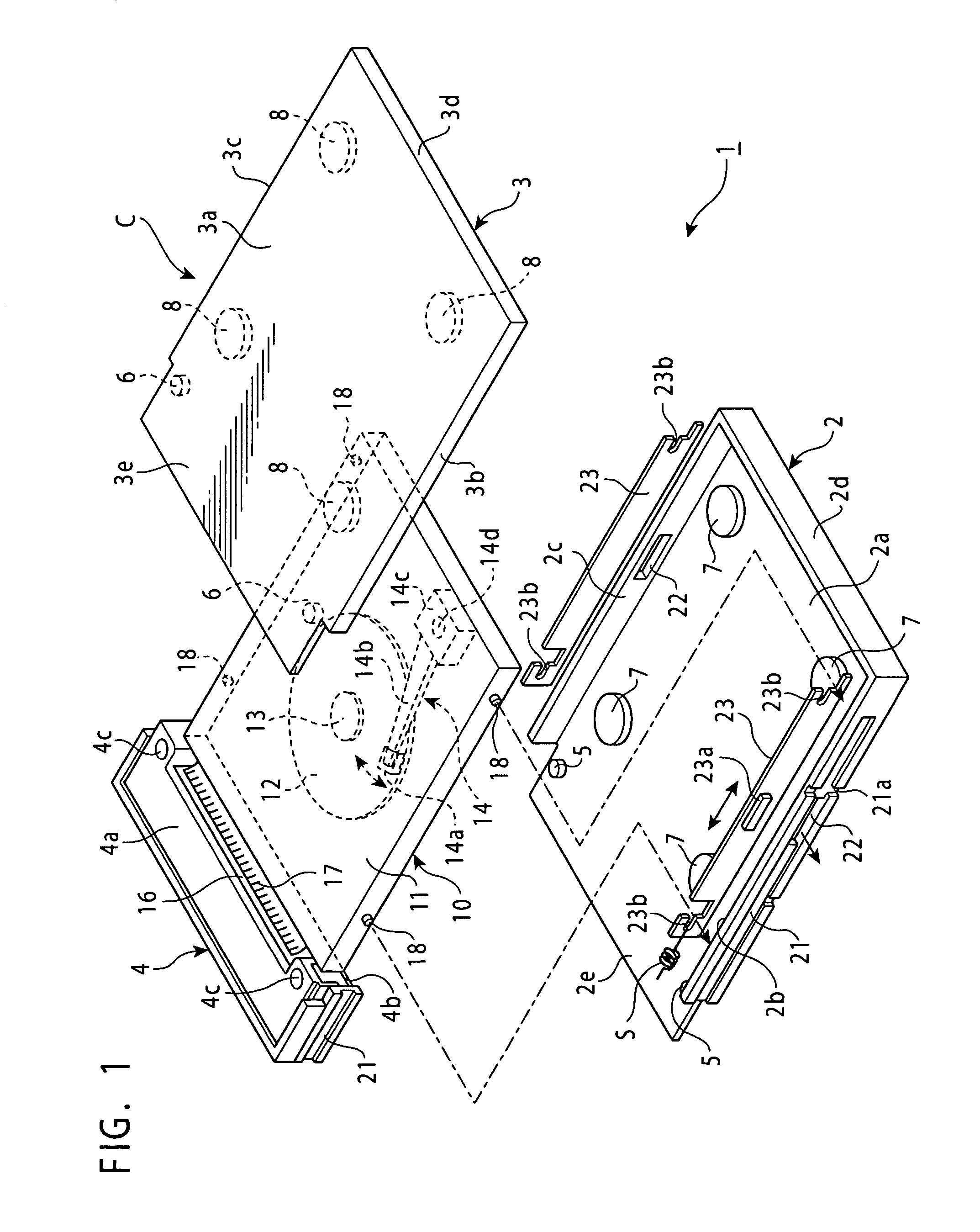
[0028]A magnetic disk device 1 shown in FIG. 1 comprises a lower case portion 2, an upper case portion 3, and a connector case portion 4. Each case portion is injection molded out of synthetic resin. The lower case portion 2 comprises a bottom surface 2a, a left surface 2b, a right surface 2c, and a rear surface 2d; has a rectangular shape; and has a recess. The front portion of the bottom surface 2a is formed as a fitting portion 2e having a somewhat smaller width. The upper case portion 3 comprises a ceiling surface 3a, a left frame 3b, a right frame 3c, and a rear frame 3d; has a rectangular shape; and has a shallow recess. The front portion of the ceiling surface 3a is formed as a fitting portion 3e having a somewhat smaller width.

[0029]The connector case portion 4 comprises a fitting recess 4a at its upper surface and a fitting recess 4b at its lower surface. The connector case portion 4 has positioning holes 4c and 4c passing through the fitting recess 4a and the fitting reces...


PUM

PropertyMeasurementUnit
forceaaaaaaaaaa
elastic modulusaaaaaaaaaa
recording densityaaaaaaaaaa

Abstract

A magnetic disk device is removable from an apparatus body includes a case, a driving unit, and a connector. The driving unit is installed in the case, and includes a magnetic disk and a rotary driver for rotationally driving the magnetic disk. The connector connects the driving unit and the apparatus body. The case includes an elastic supporting member and a locking member. The elastic supporting member elastically supports the driving unit. The locking member is movable between a locked position and an unlocked position, the driving unit being locked at the locked position and being unlocked at the unlocked position in the case. The locking member moves to the locked position and the unlocked position by operational force from the exterior of the case.

Description

BACKGROUND OF THE INVENTION[0001]1. Field of the Invention[0002]The present invention relates to a magnetic disk device that incorporates a driving unit for driving a magnetic disk and can be mounted to and removed from the body of an apparatus, and an electronic apparatus including the magnetic disk device and a body for mounting the magnetic disk device thereto.[0003]2. Description of the Related Art[0004]A removable magnetic disk device that can be mounted to and removed from the body of various apparatuses is one type of magnetic disk device usable in, for example, a vehicle-installed electronic apparatus, an information appliance, or a video recorder. This type of magnetic disk device is disclosed in Japanese Unexamined Patent Application Publication No. 6-176555 and PCT Japanese Translation Patent Publication No. 2001-502103.[0005]In this type of magnetic disk device, a hard disk is mounted as a recording medium in a case formed of a hard metal or synthetic resin. In addition,...

Claims


Application Information

Patent Timeline
Patent Type & Authority Patents(United States)
IPC IPC(8): G11B17/00G06F1/16G11B33/08G11B33/12
CPCG11B33/08G11B33/124
Inventor ABE, WATARU
Owner ALPINE ELECTRONICS INC
Why Eureka
Try Eureka