Apparatus for use in detecting circuit faults during boundary scan testing

Inactive Publication Date: 2007-07-03
CORELIS
View PDF7 Cites 7 Cited by
  • Summary
  • Abstract
  • Description
  • Claims
  • Application Information

AI Technical Summary

Problems solved by technology

For various reasons, it is becoming increasingly difficult to perform in-circuit testing using a “bed-of-nails” approach.
For example, integrated circuits (ICs) are getting smaller and IC packages are using finer and finer lead pitches making it

Method used


Image

  • Apparatus for use in detecting circuit faults during boundary scan testing
  • Apparatus for use in detecting circuit faults during boundary scan testing
  • Apparatus for use in detecting circuit faults during boundary scan testing

Examples


Embodiment Construction

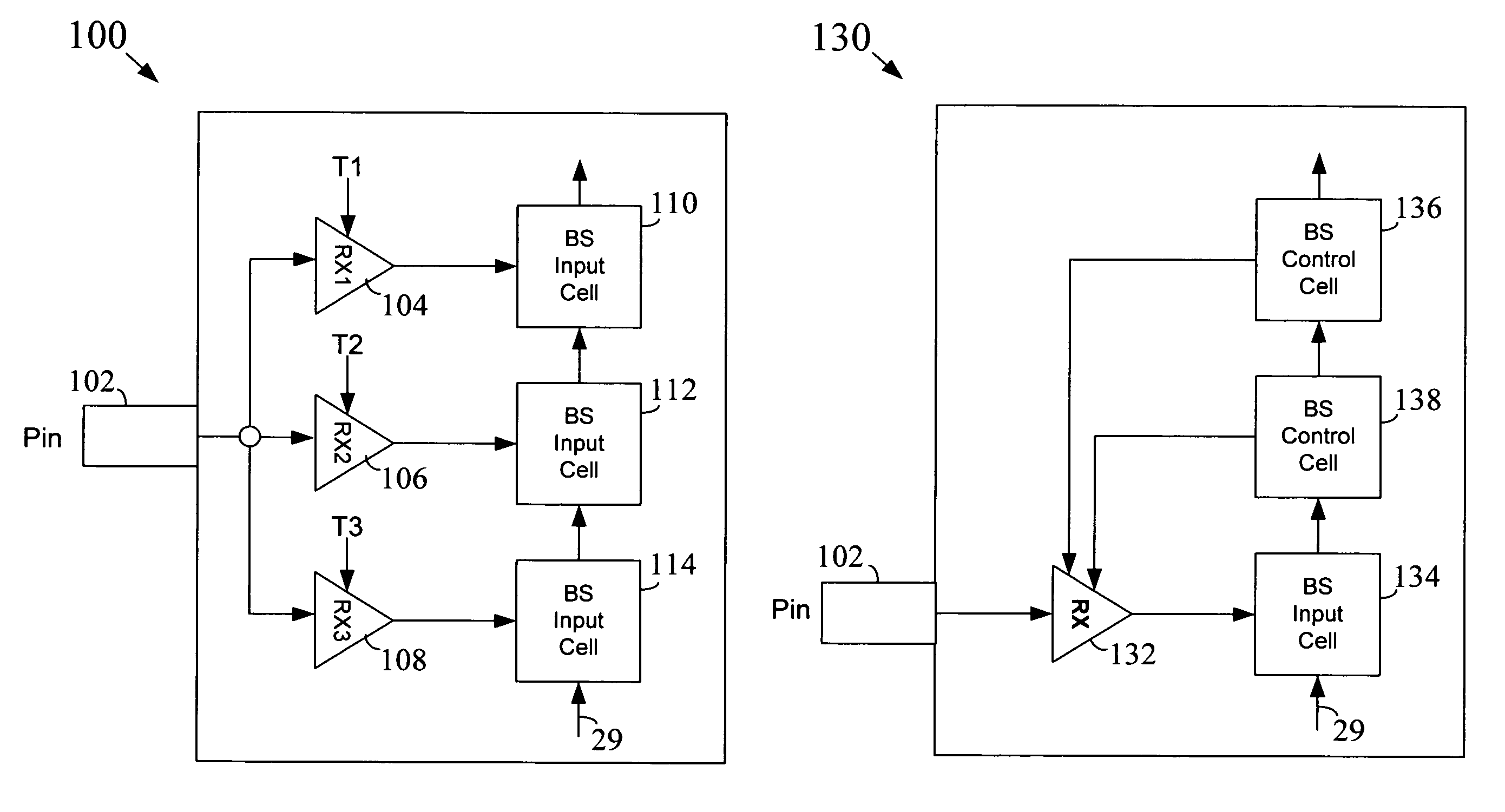
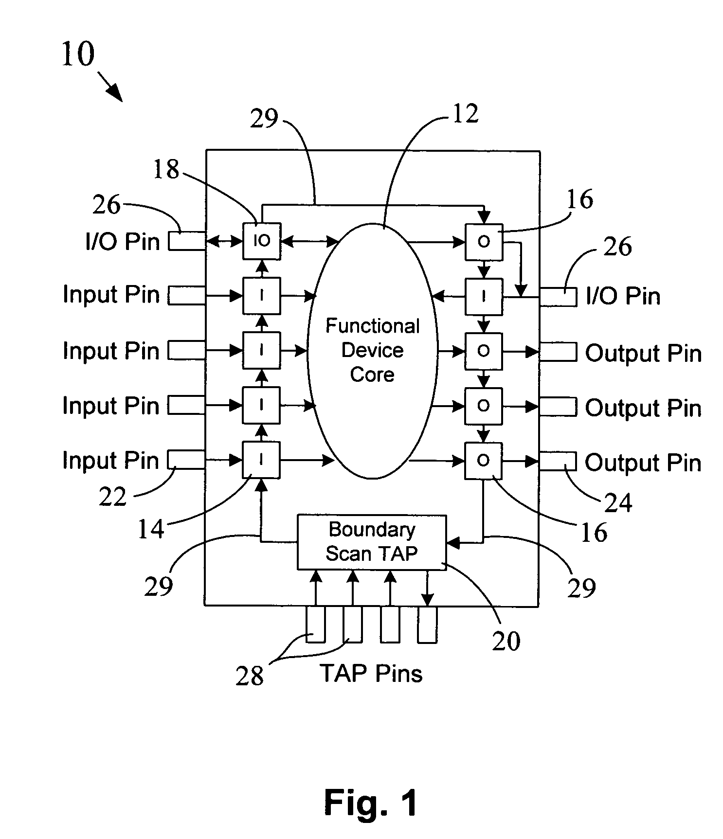
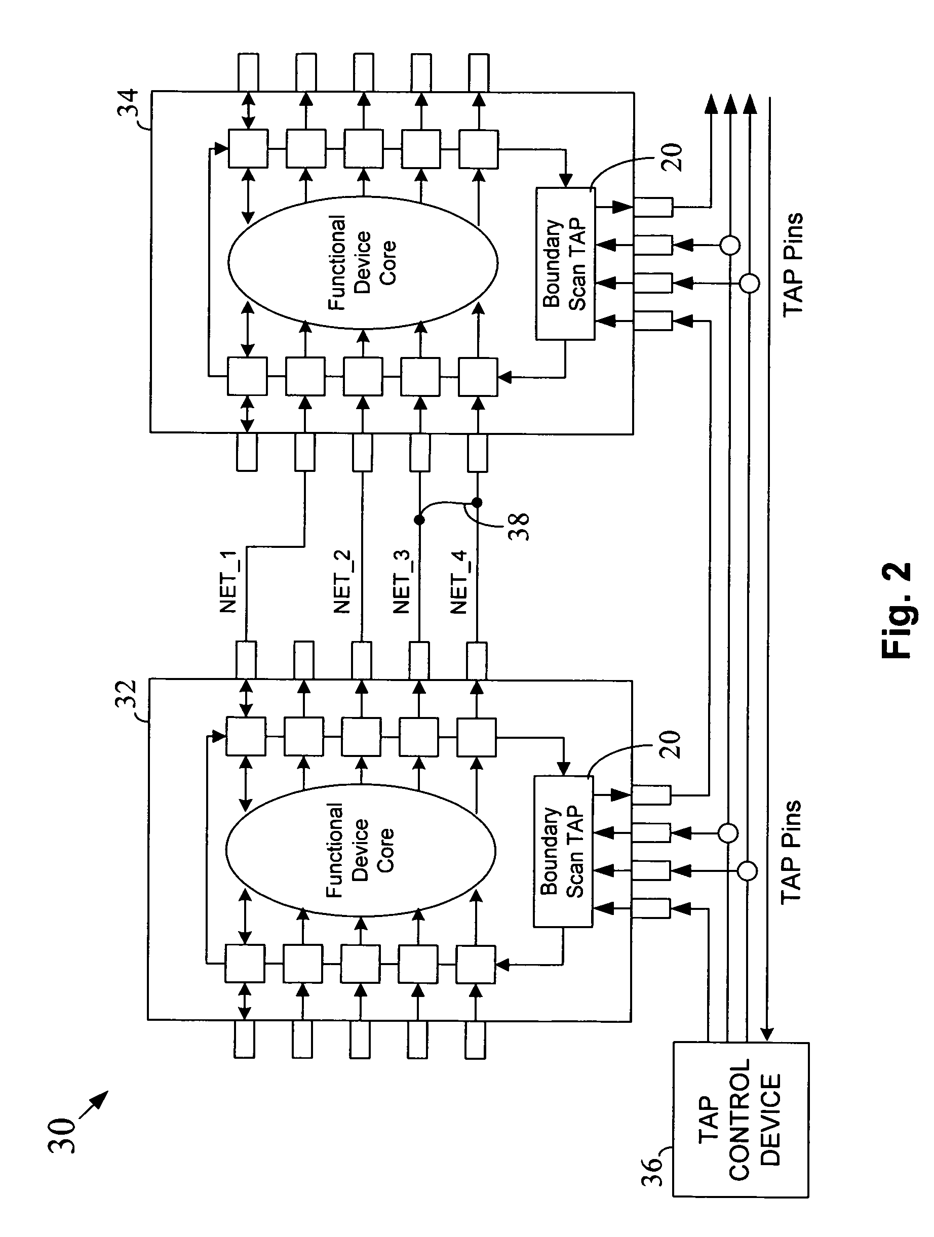
[0019]In the following detailed description, reference is made to the accompanying drawings that show, by way of illustration, specific embodiments in which the invention may be practiced. These embodiments are described in sufficient detail to enable those skilled in the art to practice the invention. It is to be understood that the various embodiments of the invention, although different, are not necessarily mutually exclusive. For example, a particular feature, structure, or characteristic described herein in connection with one embodiment may be implemented within other embodiments without departing from the spirit and scope of the invention. In addition, it is to be understood that the location or arrangement of individual elements within each disclosed embodiment may be modified without departing from the spirit and scope of the invention. The following detailed description is, therefore, not to be taken in a limiting sense, and the scope of the present invention is defined on...


PUM


Abstract

A boundary scan compatible device includes functionality for use in diagnosing the presence of bridging faults within associated circuitry. In at least one embodiment, a boundary scan compatible device includes functionality for detecting an intermediate signal level on an electrical node of the device (e.g., a pin on a circuit package, etc.) that is indicative of a bridging fault. Various structures are provided that are capable of detecting an intermediate signal level.

Description

FIELD OF THE INVENTION[0001]The invention relates generally to circuit testing and, more particularly, to techniques and structures for use in performing boundary scan testing.BACKGROUND OF THE INVENTION[0002]Printed circuit board testing has traditionally been performed using bed-of-nails in-circuit test equipment. This equipment typically includes a test fixture having a multitude of test probes (known as a “bed of nails”) that, when coupled to a circuit board, simultaneously contacts numerous electrical nodes on the circuit board, thereby providing electrical access to the components on the board. Various electrical tests may then be performed on the circuit components, usually under computer control. For various reasons, it is becoming increasingly difficult to perform in-circuit testing using a “bed-of-nails” approach. For example, integrated circuits (ICs) are getting smaller and IC packages are using finer and finer lead pitches making it difficult to contact all of the desir...

Claims


Application Information

Patent Timeline
IPC IPC(8): G01R31/28
CPCG01R31/318572
Inventor YELLIN, CARMYBLASBERG, MENACHEM
Owner CORELIS
Why Eureka
Try Eureka