
Mounting device of sprinkler

a technology of mounting device and sprinkler, which is applied in the direction of branching pipes, ceilings, shores, etc., can solve the problems of complicated assembling operation, increased time taken to carry out the operation, and increased complexity of the assembling operation, so as to facilitate the assembling operation and reduce the time taken to carry

Active Publication Date: 2007-07-10
PARATECH
View PDF3 Cites 66 Cited by
  • Summary
  • Abstract
  • Description
  • Claims
  • Application Information

AI Technical Summary

Benefits of technology

The present invention provides a mounting device for a sprinkler that is easy to assemble and reduces the time required for installation. The device can be used with various sized ceiling support rails and sprinklers. The device includes a mounter and a locking member. The mounter has a main body with side plates and an upper plate, with a rail mounting portion, a support bar fixing portion, and a locking member. The locking member has a first plate with slots and second plates for supporting the support bar. The device also includes a locking bolt for fixing the support bar. The technical effects of the invention include simplifying the assembly process, reducing installation time, and providing flexibility for different sized sprinklers and support rails.

Problems solved by technology

As seen in U.S. Pat. No. 6,260,810, the mounting device in accordance with the conventional art is disadvantageous in that an assembling operation is complicated and the time taken to carry out the operation is lengthened because of threading of locking bolts for fixing the mounting device to the ceiling support rail and to the reducer support beam.
Particularly, the two locking bolts are threaded in perpendicular directions to each other, which makes the assembling operation more complicated.

Method used


Image

  • Mounting device of sprinkler
  • Mounting device of sprinkler
  • Mounting device of sprinkler

Examples


Embodiment Construction

[0023]Reference will now be made in detail to the preferred embodiments of the present invention, examples of which are illustrated in the accompanying drawings.

[0024]There may exist a plurality of embodiments of a mounting device of a sprinkler in accordance with the present invention, and the most preferred embodiments will be explained.

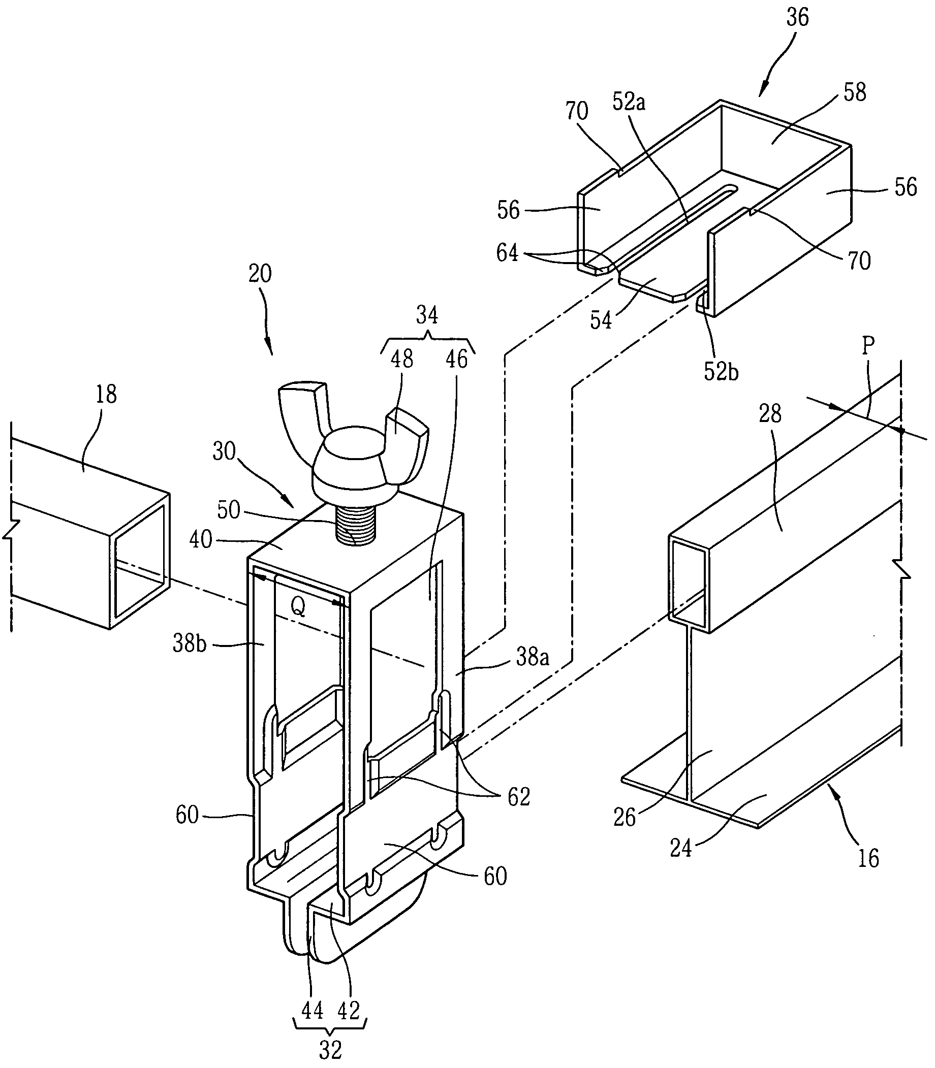
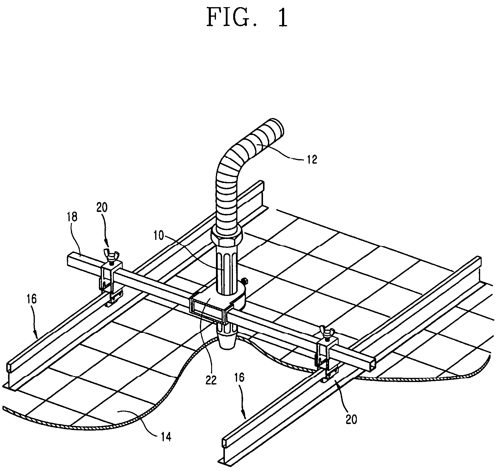
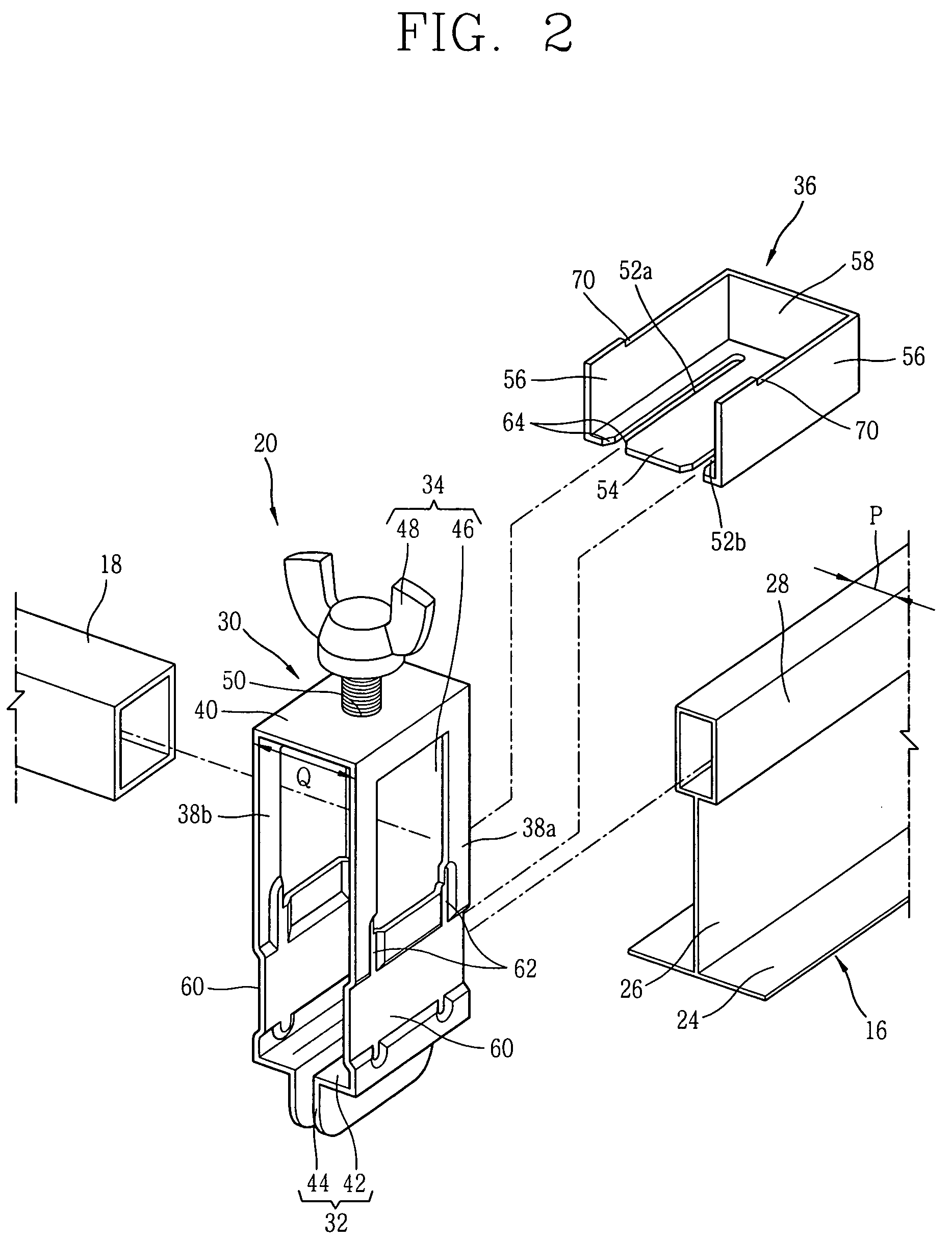
[0025]FIG. 1 is a perspective view showing that a sprinkler in accordance with the present invention is fixed to a ceiling by a mounting device of the sprinkler, FIG. 2 is an exploded perspective view of the mounting device of the sprinkler in accordance with the first embodiment the present invention, and FIG. 3 is a side view of the mounting device of the sprinkler in accordance with the first embodiment of the present invention;

[0026]The sprinkler in accordance with the present invention includes: a sprinkler reducer 10 fixed inside a ceiling 14; a sprinkler head (not shown) mounted at a lower end of the sprinkler reducer 10 and disposed to be e...


PUM


Abstract

A mounting device of a sprinkler comprises: a main body provided with a pair of side plates and an upper plate disposed on upper portions of the side plate; a rail mounting portion formed at lower ends of the side plates and insertedly fixed to a support rail; a support bar fixing portion formed at an upper side of the main body, for supporting the support bar; and a locking member inserted in the side plates in a lateral direction, for preventing the rail mounting portion from being separated from the support rail.

Description

BACKGROUND OF THE INVENTION[0001]1. Field of the Invention[0002]The present invention relates to a mounting device of a sprinkler, and particularly, to a mounting device of a sprinkler capable of facilitating an operation for mounting a sprinkler to a ceiling and of reducing the time taken to carry out the operation.[0003]2. Description of the Background Art[0004]In general, the sprinkler includes a sprinkler reducer mounted inside a ceiling; a sprinkler head mounted to a lower end of the sprinkler reducer and disposed to be exposed to the outside of the ceiling, for spraying of water for fire protection; and a water supply hose connected to an upper end of the sprinkler reducer, through which water needed for fire protection is supplied.[0005]Here, the sprinkler reducer is mounted to an inner surface of the ceiling by a mounting device of a sprinkler.[0006]The mounting device of the sprinkler in accordance with the conventional art includes: a pair of ceiling support rails fixed to...

Claims


Application Information

Patent Timeline
Patent Type & Authority Patents(United States)
IPC IPC(8): B42F13/00F16L3/08E04B9/00F16B7/04
CPCE04B9/006F16B7/0493Y10T403/4602Y10T403/73Y10T24/303Y10T24/307Y10T403/7001F16B2200/67F16L3/08
Inventor SHIM, DAE-MIN
Owner PARATECH
Learn More