Adaptor unit and optical plug

a technology of adaptors and optical plugs, applied in the field of adaptor units, can solve the problems of unsatisfactory conventional optical plugs b>10/b>′, the efficiency of maintaining each ferrule front facet is worse, etc., and achieve the effect of improving the maintenance efficiency of optical plugs or optical connectors, easy and rapid opening, and easy and rapid operation

Active Publication Date: 2007-07-10
CANARE ELECTRIC
View PDF7 Cites 1 Cited by
  • Summary
  • Abstract
  • Description
  • Claims
  • Application Information

AI Technical Summary

Benefits of technology

[0024]Effects to be obtained by the present invention are explained as follows.
[0025]That is, according to the first aspect of the present invention, the adaptor main body and the dividing sleeve holder are fit at the fitting part and the dividing sleeve holder and a predetermined jig are also fit at the fitting part. When the jig is connected to the dividing sleeve holder, the whole body of the adaptor unit can be taken out from the opening part of the optical connector only by pulling the jig.
[0026]Accordingly, by employing the first embodiment of the present invention, the portion around the front facet of the ferrule can be easily and rapidly opened remarkably wide in an urgent situation in its maintenance or operation, and that enables to find out dirt or stain at the front facet of the ferrule easily and rapidly. Consequently, maintenance efficiency of the optical plug or the optical connector can be remarkably improved.
[0027]According to the second aspect of the present invention, each dividing sleeve holder is fit to the fitting part of the adaptor main body. That enables to expose each front facet of all the ferrules at front side of the opening part of the optical plug by pulling the jig only once.
[0028]As a result, frequency of operating the jig may be decreased in fewer than half in maintenance of the optical plug comprising plural ferrules, and maintenance efficiency of the optical plug can be improved.
[0029]Alternatively, fitting structure in which a male screw and a female screw are screwed together (the third aspect of the present invention) can be employed for forming the fitting part described above concretely and easily. The fitting part, however, may not be necessarily have those structures in the present invention but can have other structure.

Problems solved by technology

Consequently, efficiency for maintaining each ferrule front facet becomes worse.
In short, the conventional optical plug 10′ has not been desirable.

Method used


Image

  • Adaptor unit and optical plug
  • Adaptor unit and optical plug
  • Adaptor unit and optical plug

Examples


first embodiment

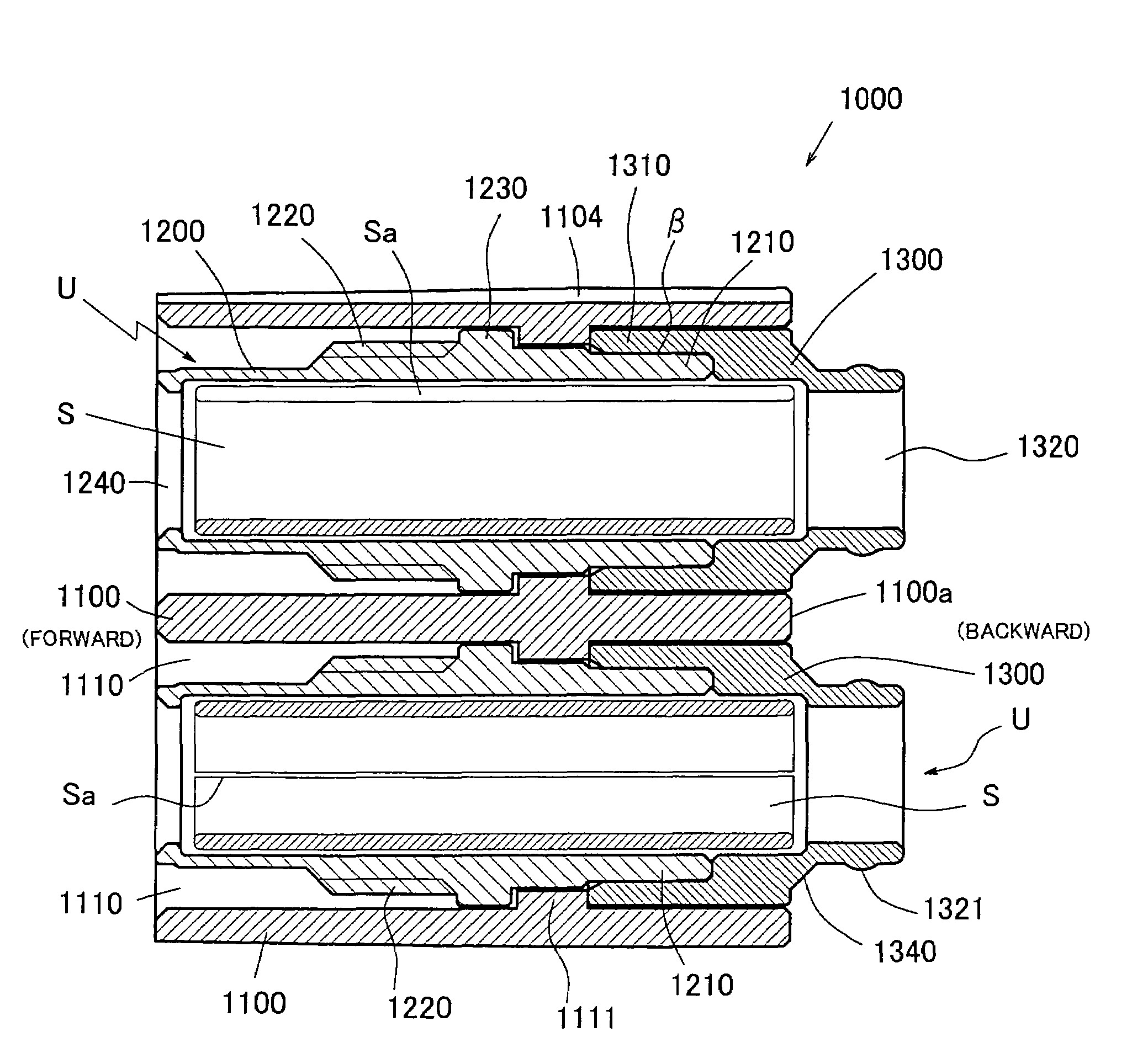
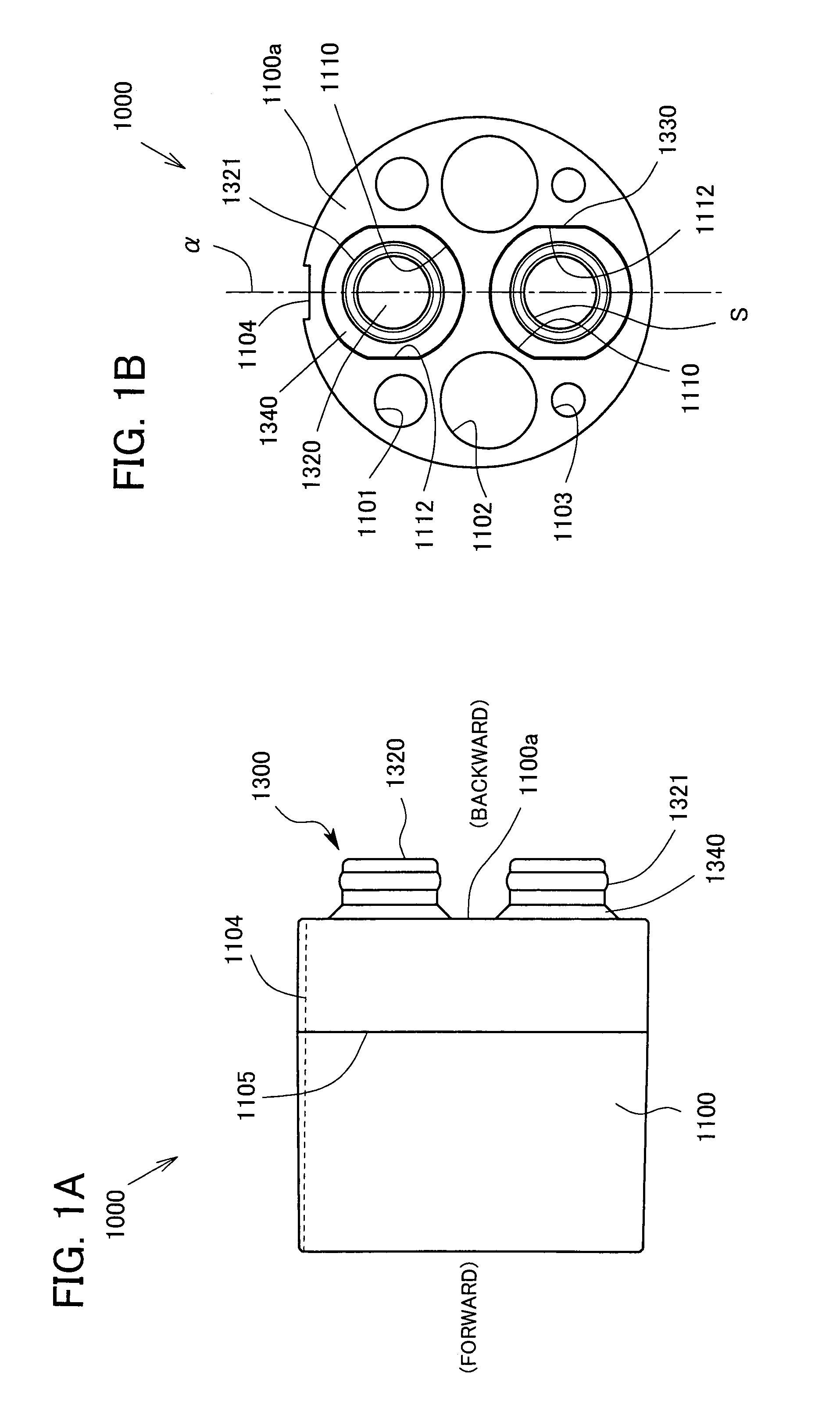
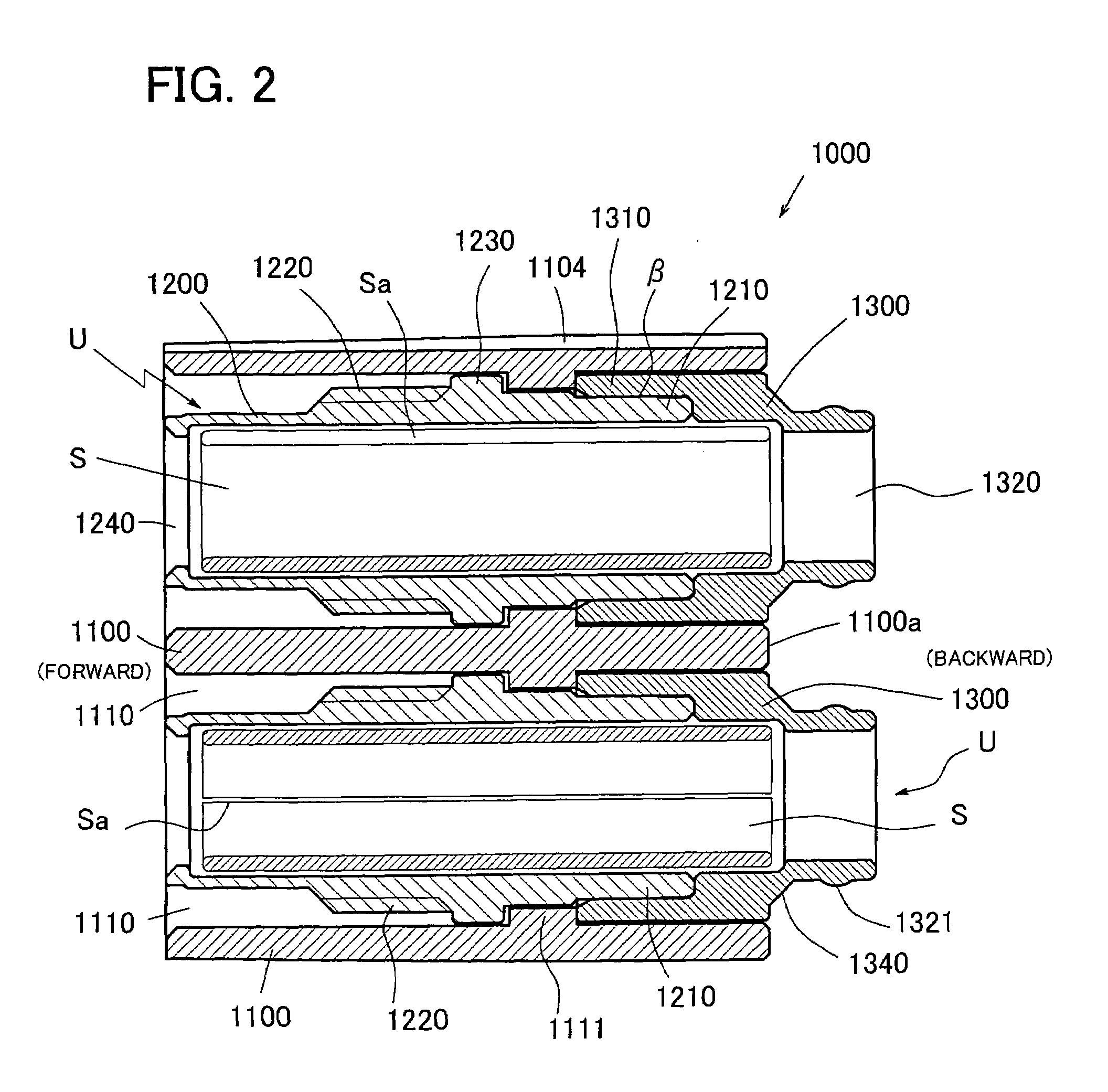
[0060]FIG. 1A is a side view of an adaptor unit 1000 in the first embodiment of the present invention. An adaptor main body 1100 is made of an insulator, and a shallow groove 1104 is formed in the optical axis direction at the upper portion of its′ external surface formed in an approximately cylindrical shape. And a further shallow step 1105 is formed at the external surface of the cylindrical main body in circular direction. From the bottom surface 1100a of the adaptor main body 1100, each back end part 1320 of two dividing sleeve holders 1300 in total, each of which formed in an cylindrical shape, sticks out backward. A hill part 1321 is formed in an approximately ring shape at the external surface of the back end part 1320.

[0061]FIG. 1B is a back view of the adaptor unit 1000 in the first embodiment of the present invention. Each adaptor unit 1000 is formed approximately symmetrical to a sectional plane α. Six through-holes (1101, 1102, 1110) in total are formed in the adaptor ma...

second embodiment

[0085]FIGS. 8A and 8B show a front and top view and a sectional view of an optical plug 4000 in a second embodiment of the present invention. The optical plug 4000 comprises the adaptor unit 1000 in the first embodiment of the present invention. An agraffe 4400, a cramp body 4500, a pressure-bonding sleeve 4600, and a gum tube GT consist of a cable fixing part of the optical plug 4000. In the second embodiment, the central axis of an approximately cylindrical female plug shell 4100 is the z axis and the direction from the gum tube GT to an edge 4000a of the female plug 4000 is the positive direction of the z axis.

[0086]A slide sleeve 4150 formed in an approximately cylindrical shape is supported by a screw 4151 resiliently and guided to the z axis direction by a guide pin PN3, which enables to shuttle in the z axis direction in a predetermined range. Accordingly, a latching sleeve LS is pumped in the slide sleeve 4150 in diameter direction of the female plug shell 4100.

[0087]An inse...

other modified embodiment

[0092]While the present invention has been described with reference to the above embodiments as the most practical and optimum ones, the present invention is not limited thereto, but may be modified as appropriate without departing from the spirit of the invention. By applying and modifying the embodiment, effect of the present invention can be obtained.


PUM


Abstract

A screwing part 1220 is inserted into a large through-hole 1110 from its front side and is screwed together with a male screw part of a jig. A convex part 1230 in an approximately ring shape is formed at a back end part of the screwing part 1220. The convex part 1230 is adjacent to a fitting part 1111 which is made of an approximately ring convex part projecting toward inside of the large through-hole 1110. The back of the fitting part 1111 is adjacent to a front end opening part 1310 of a back tubular part 1300. In short, the fitting part 1111 of the adaptor main body 1110 is sandwiched between the convex part 1230 and the front end opening part 1310. By inserting and pressing the back end opening part 1210 of the front tubular part 1200 into the front end opening part 1310 of the back tubular part 1300, the front tubular part 1200 and the back tubular part 1300 are connected and fixed with each other. Sign β represents their pressing part.

Description

TECHNICAL FIELD [0001]The present invention relates to an adaptor unit comprising an optical plug which connects each front facet of two ferrules facing with each other and is installed at either male or female opening part.BACKGROUND ART [0002]Conventionally, a Japanese Utility Patent Application Laid-open No. H6-2306 has disclosed an adaptor unit comprising an optical plug which connects each front facet of two ferrules facing with each other and is installed at either male or female opening part in its FIGS. 1 and 2. FIG. 9 of the present application illustrates its structure. The adaptor (19) comprising components such as a dividing sleeve (22) disclosed in the Japanese Utility Patent Application Laid-open No. H6-2306 has been common and well-known.[0003]Recently, as shown in FIGS. 10A-10C, a dividing sleeve unit (u1) is formed by using an approximately tubular dividing sleeve holder (K1, K2) comprising a dividing sleeve (S), and an assembly of components (referred as an adaptor...

Claims


Application Information

Patent Timeline
Patent Type & Authority Patents(United States)
IPC IPC(8): G02B6/26G02B6/36G02B6/38G02B6/42
CPCG02B6/3877G02B6/4292
Inventor TAKAHASHI, TETSUOKOMATSUBARA, MANABU
Owner CANARE ELECTRIC
Why Eureka
Try Eureka