Decoration-used mold unit

a mold and decoration technology, applied in the direction of woodworking apparatus, using mechanical means, drilling/boring measurement devices, etc., can solve the problems of time-consuming and laborious, lock or bolt cannot be snugly installed into the sink, and the border is difficult to be straight, so as to facilitate cutting or milling

Inactive Publication Date: 2007-07-10
YANG KUN YING
View PDF17 Cites 7 Cited by
  • Summary
  • Abstract
  • Description
  • Claims
  • Application Information

AI Technical Summary

Benefits of technology

[0005]It is therefore a primary object of the present invention to provide a decoration-used mold unit for defining a border on a work piece t

Problems solved by technology

It is so hard to have the border straight.
As a result, it often takes place that the lock or the bolt cannot be snugly install

Method used


Image

  • Decoration-used mold unit
  • Decoration-used mold unit
  • Decoration-used mold unit

Examples


Embodiment Construction

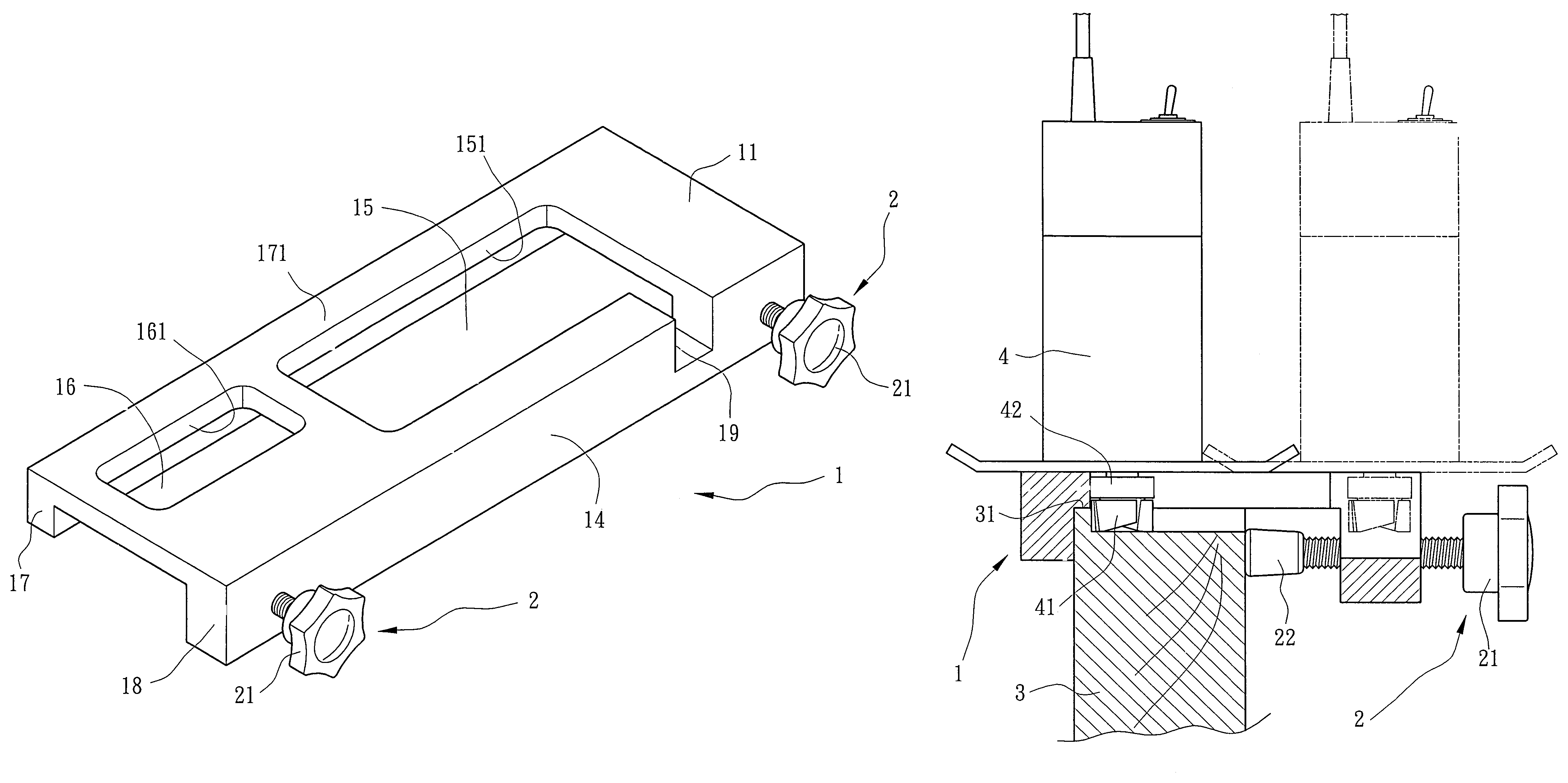
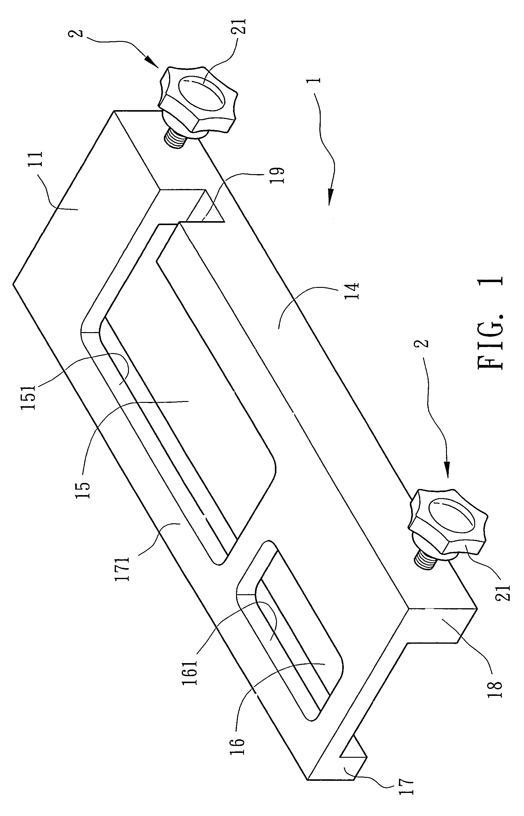
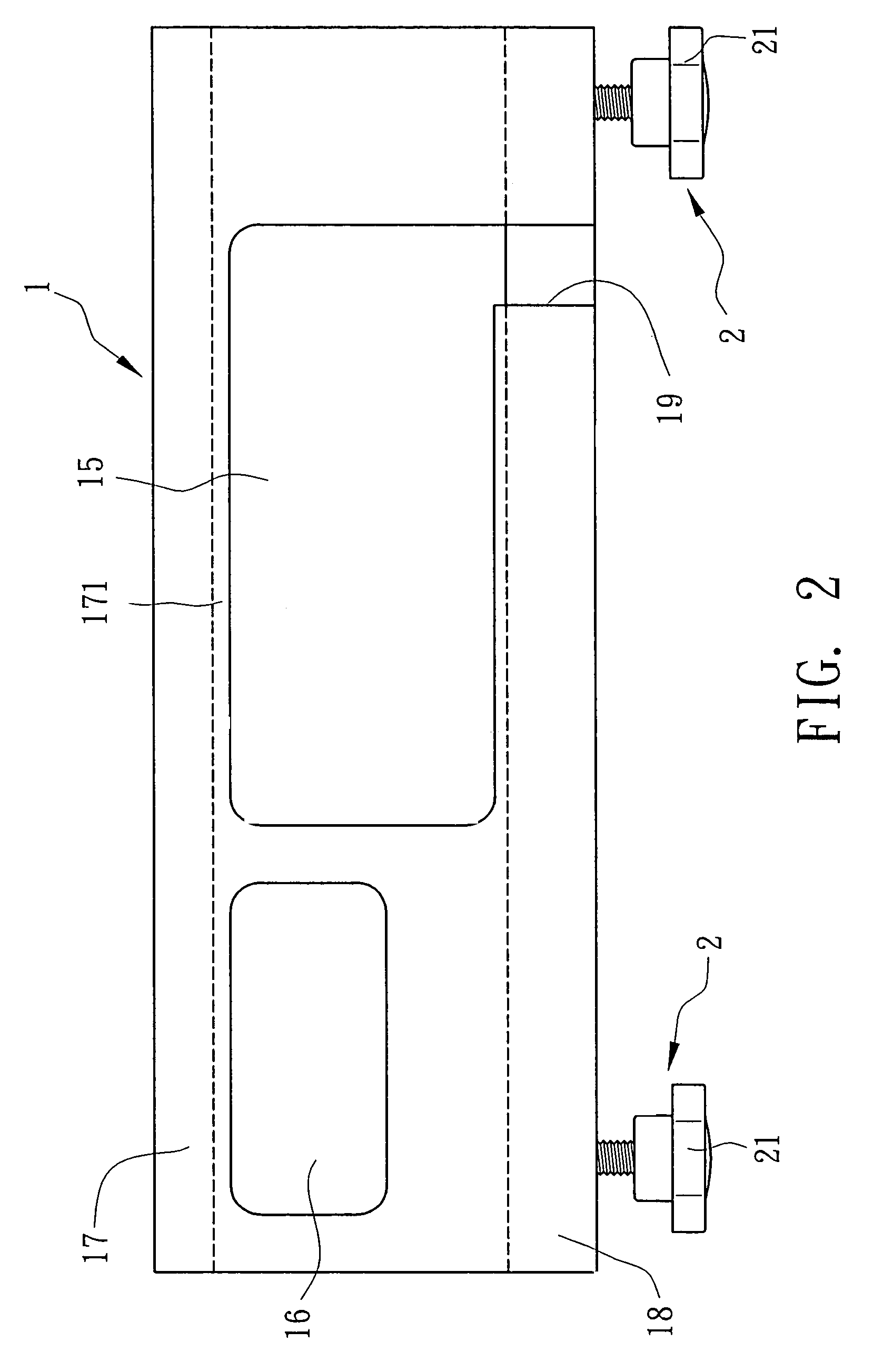
[0014]Please refer to FIGS. 1 to 3. The decoration-used mold unit of the present invention serves to define a range of a sink of a door board for a bolt and a door lock.

[0015]The decoration-used mold unit includes an elongated rectangular main body 1 having a top face 11 and a bottom 12 opposite to the top face 11. The main body 1 also has a first side 13 and a second side 14 opposite to each other. The top and bottom faces 11, 12 are bridged between the first and second sides 13, 14. The main body 1 is formed with a first window 15 for processing a sink for a bolt and a second window 16 for processing a sink for a door lock. The first window 15 has a sidewall 151 perpendicular to the bottom face. The second window 16 has a sidewall 161 perpendicular to the bottom face. A first chucking section 17 protrudes from the bottom face 12 in a position adjacent to the first side 13. A width 171 is reserved between the sidewalls 151, 161 and the first chucking section 17. A second chucking s...


PUM


Abstract

A decoration-used mold unit for defining a border on a work piece to facilitate cutting or milling. The mold unit includes an elongated rectangular main body formed with a first window for processing a first sink and a second window for processing a second sink. A first chucking section protrudes from a first side of the main body. A second chucking section protrudes from a second side of the main body. At least one abutting member is adjustably arranged at the second chucking section. The first chucking section and the abutting member respectively abut against two opposite sides of the work piece to clamp the work piece. In the processing procedure, the blade is restricted within the first and second windows so that the work piece will not be over-milled and the borders of the sinks keep straight.

Description

BACKGROUND OF THE INVENTION[0001]The present invention is related to a decoration-used mold unit for defining a border on a work piece to facilitate cutting or milling. In the milling procedure, the blade is restricted within a certain range without over-cutting the work piece.[0002]In decoration, when installing a wooden door, it is necessary for a carpenter to use a chisel to chisel the door to form desired channels or sinks for mounting a lock and a bolt.[0003]Please refer to FIG. 5. A carpenter first marks the boarder 8 of the installation region of the lock on the door and then uses the chisel 7 to chisel the border 8. Then the region within the border 8 is chiseled by a certain thickness to form a sink 81 in accordance with the bolt. However, during the chiseling, a certain thickness 82 must be reserved near the face of the door to keep the door face tidy.[0004]The border is manually chiseled one by one with the chisel 7. It is so hard to have the border straight. As a result,...

Claims


Application Information

Patent Timeline
IPC IPC(8): B23C1/20B23C3/00B27C5/10
CPCB27F5/12E04F21/003E05B17/06E05D11/0009E05Y2900/148Y10T409/306496Y10T409/306384Y10T408/563Y10T408/567Y10T409/303696Y10T409/304424
Inventor YANG, KUN-YING
Owner YANG KUN YING
Why Eureka
Try Eureka