Device for testing a test specimen for surface faults by magnetization means and by means of induction probes as measurement sensors

a technology of induction probe and test specimen, which is applied in the direction of magnetic measurement, instruments, cores/yokes, etc., can solve the problems of narrow limits on the service life of the device, inability to quickly and economically adapt to different dimensions, and insufficient heat dissipation, so as to achieve easy and economical adaptation to different dimensions, high heat dissipation, and high magnetizing power. , the effect of high service li

Active Publication Date: 2007-07-10
PRUTECHNIK DIETER BUSCH AG
View PDF6 Cites 8 Cited by
  • Summary
  • Abstract
  • Description
  • Claims
  • Application Information

AI Technical Summary

Benefits of technology

[0009]Therefore, the object of the invention is to make a device for testing a test specimen for surface faults by magnetization means for delivering a magnetic flux into the specimen and by means of induction probes as measurement sensors such that it can be easily and economically adapted to different test specimens and is characterized by high heat dissipation in order to achieve both high magnetizing power and also service life.
[0011]The magnetic flux conductor can be made, for example, triangular, square, or preferably annular. By the measure as claimed in the invention to arrange two yoke legs with one exciter winding each opposite one another such that between the opposing ends, the gap ends, a gap is formed, and to connect the outside ends of the yoke legs to one another via a magnetic flux conductor, this arrangement can be economically produced from a powder composite material and can be adapted to test specimens of different dimensions because the powder composites can be easily worked by sawing, milling and grinding. The outside ends of the yoke legs can rest for example on the magnetic flux conductor. Alternatively the magnetic flux conductor can rest on the outside ends of the yoke legs. The heat loss produced by the remagnetization can be dissipated very well via the magnetic flux conductor. The device as claimed in the invention is therefore suited for high magnetizing powers and is characterized by a long service life.

Problems solved by technology

The indicated known devices are subject to the first disadvantage that they cannot be quickly and economically adapted to different dimensions, especially the cross sections, of the test specimens.
A second disadvantage lies in the inadequate heat dissipation which, as the third disadvantage, sets narrow limits on the service life of the device, and finally, limits the magnetizing power as the fourth disadvantage.
The shape of the coil cores used in the indicated devices can only be changed at high costs for bobbin cores which have been wound insulated.

Method used


Image

  • Device for testing a test specimen for surface faults by magnetization means and by means of induction probes as measurement sensors
  • Device for testing a test specimen for surface faults by magnetization means and by means of induction probes as measurement sensors
  • Device for testing a test specimen for surface faults by magnetization means and by means of induction probes as measurement sensors

Examples


Embodiment Construction

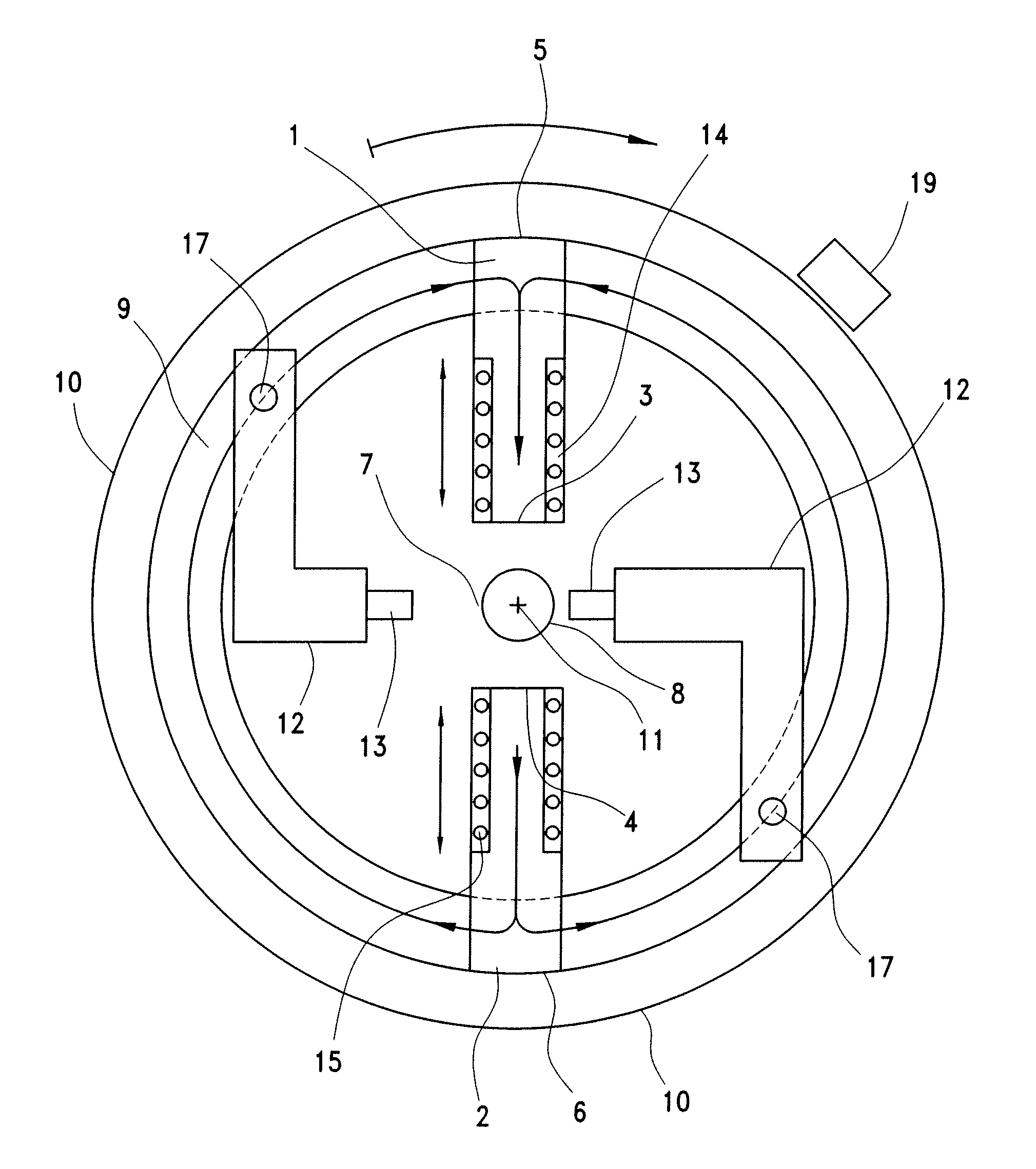
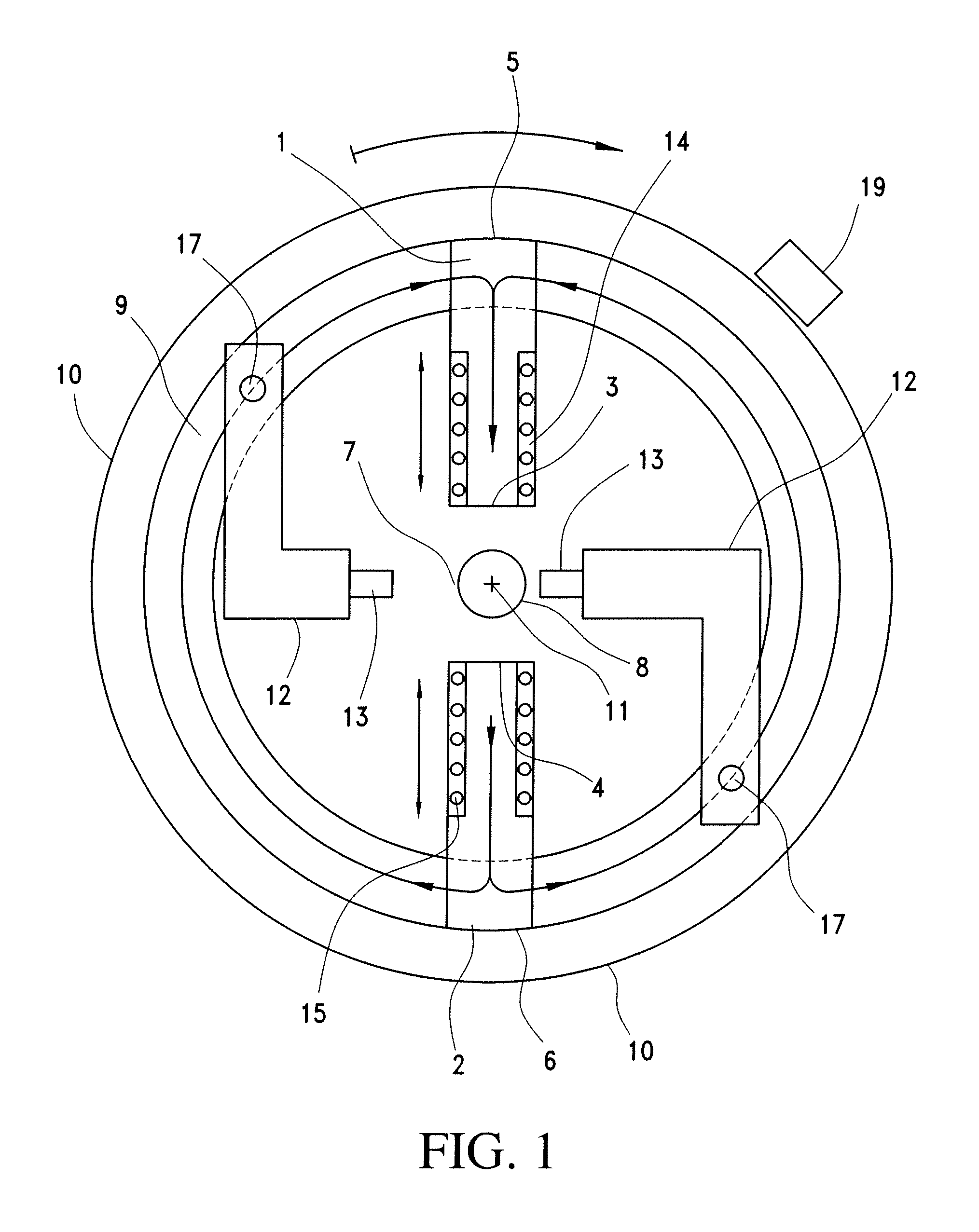
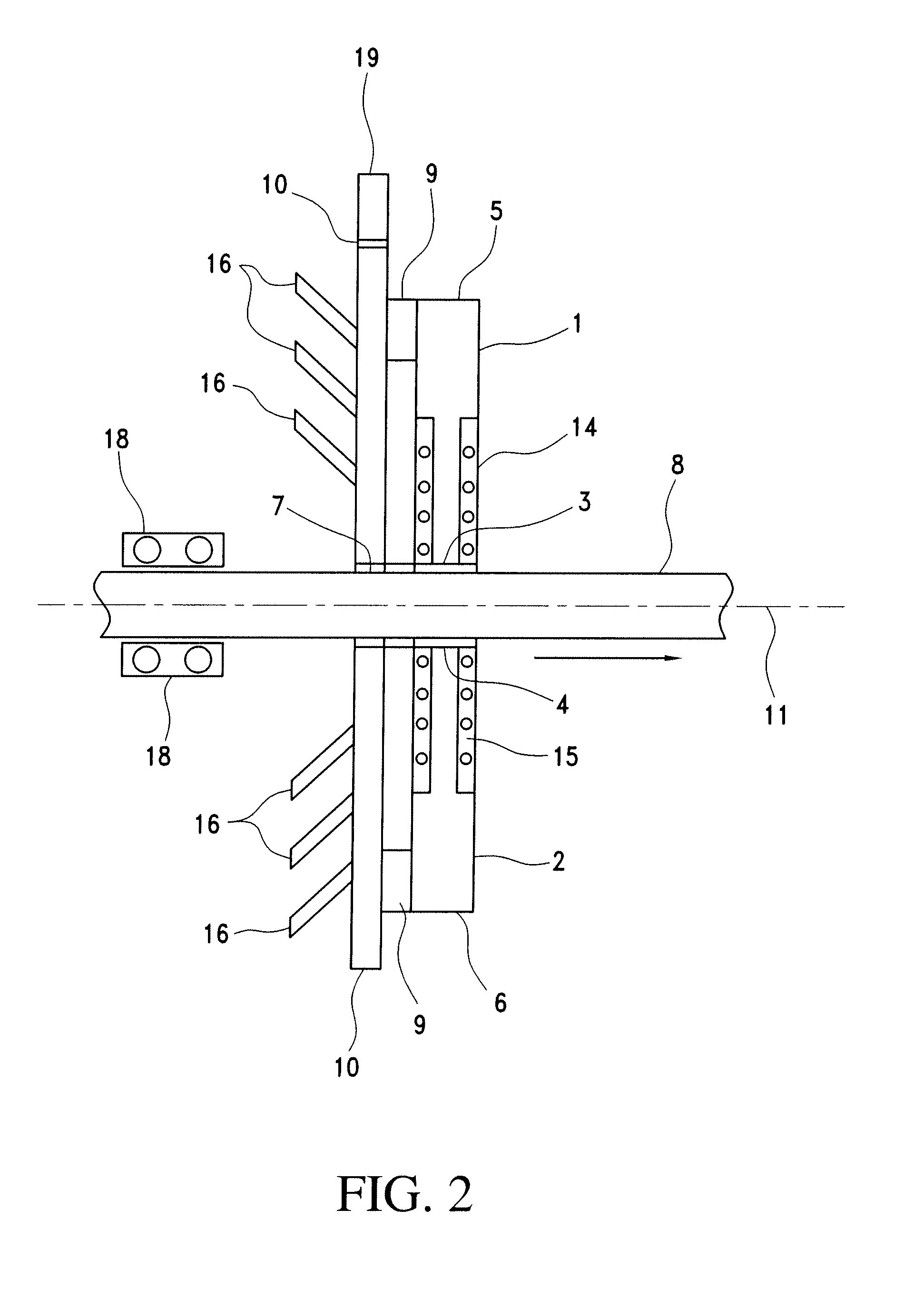
[0019]In FIGS. 1 and 2, the two yoke legs 1, 2 are arranged vertically opposite one another such that, between their opposing ends 3, 4, a gap 7 is formed through which a test specimen 8 is guided perpendicular to the plane of the FIG. 1 (in the direction of the arrow in FIG. 2). The exciter windings 14, 15 sit on the gap-forming ends 3, 4 of the yoke legs 1, 2. The outside ends 5, 6, opposite the gap-forming ends 3, 4 are connected via an annular magnetic flux conductor 9 which sits on a rotating disk 10. On the magnetic flux conductor 9, there are two levers 12 which can be pivoted around an axis 17 and on each of which a respective induction coil 13 sits. To adapt to test specimens of different cross section, the yoke legs 1, 2 can be movably mounted on an annular magnetic flux conductor 9 in the direction of the double arrows and to be fixed in the desired position.

[0020]The yoke legs 1, 2 and the magnetic flux conductor 9 are preferably produced from a powder material. On the b...


PUM

PropertyMeasurementUnit
magnetizationaaaaaaaaaa
magnetic fluxaaaaaaaaaa
sizeaaaaaaaaaa

Abstract

A device for testing a test specimen for surface faults is equipped for delivering a magnetic flux into the specimen and has induction probes measurement sensors. At least two yoke legs have opposed gap-forming ends with oppositely poled exciter coils between which the test specimen can be guided. Outside ends of the yoke legs opposite the gap-forming ends are connected to one another by a magnetic flux conductor so that the magnetic flux runs perpendicular to the lengthwise direction through the test specimen. To adapt to test specimens of different cross section, the yoke legs can be moved and fixed. Testing of test specimens by means of high-energy magnetic alternating fields improved because the high heat losses produced in this process are adequately dissipated. The device is especially well suited to determine the quality of bars, pipes and the like in a hot rolling mill with high-energy alternating magnetic fields.

Description

BACKGROUND OF THE INVENTION[0001]1. Field of the Invention[0002]The invention relates to a device for testing a test specimen for surface faults by magnetization means by delivering a magnetic flux into the specimen and using induction probes as measurement sensors, the induction probes being capable of turning around the specimen, which can be guided in the lengthwise direction, in order to scan it helically.[0003]2. Description of Related Art[0004]These devices are used to determine, for example, surface faults on metallic articles with a round profile, such as billets, bars, steel pipes and the like, while these articles, which can have high temperatures depending on the choice of fabrication process, run through a production line, for example, a mill train.[0005]Magnetization means magnetize the test specimen such that the faults near the surface produce a stray flux which can be detected by means of induction probes. Faults in and under the surface of a test piece cause, for ex...

Claims


Application Information

Patent Timeline
Patent Type & Authority Patents(United States)
IPC IPC(8): G01N27/72G01N27/82G01R33/12G01N27/76G01N27/90H01F3/08
CPCG01N27/9026G01N27/904H01F3/08G01N27/902
Inventor ZIMMERMANN, BERND
Owner PRUTECHNIK DIETER BUSCH AG
Why Eureka
Try Eureka