Telecommunications routing

a telecommunications signal and routing technology, applied in the field of telecommunications routing, can solve the problems of address exhaustion (the inability to re-use an address), additional cost of mobility, cost of tunnelling, etc., and achieve the effect of preventing unwanted routing loops

Inactive Publication Date: 2007-07-10
BRITISH TELECOMM PLC
View PDF38 Cites 29 Cited by
  • Summary
  • Abstract
  • Description
  • Claims
  • Application Information

AI Technical Summary

Benefits of technology

[0019]This aspect of the invention may be implemented in order to prevent unwanted routing loops during a routing direction process.

Problems solved by technology

The additional cost of mobility is the provision of this Home Agent / Foreign Agent interface, and especially with packet systems, the cost of tunnelling (forwarding messages from one address to another), address exhaustion (the inability to re-use an address from which forwarding is taking place) and triangular routing.
Drawbacks with the HAWAII proposals include the concentration of Mobile IP tunnels in few nodes in the core of the network, the domain root routers, such that failure of any of these nodes may result in large-scale failure of all Mobile IP state and associated sessions handled by the failing node.
Furthermore, since all routing from outside the home domain into the home domain, and in the reverse direction, must occur via the home domain root router, failure of the home domain root router may also result in large-scale failure.
As the mobile moves between access nodes, the routing paths created become less efficient.

Method used


Image

  • Telecommunications routing
  • Telecommunications routing
  • Telecommunications routing

Examples


Embodiment Construction

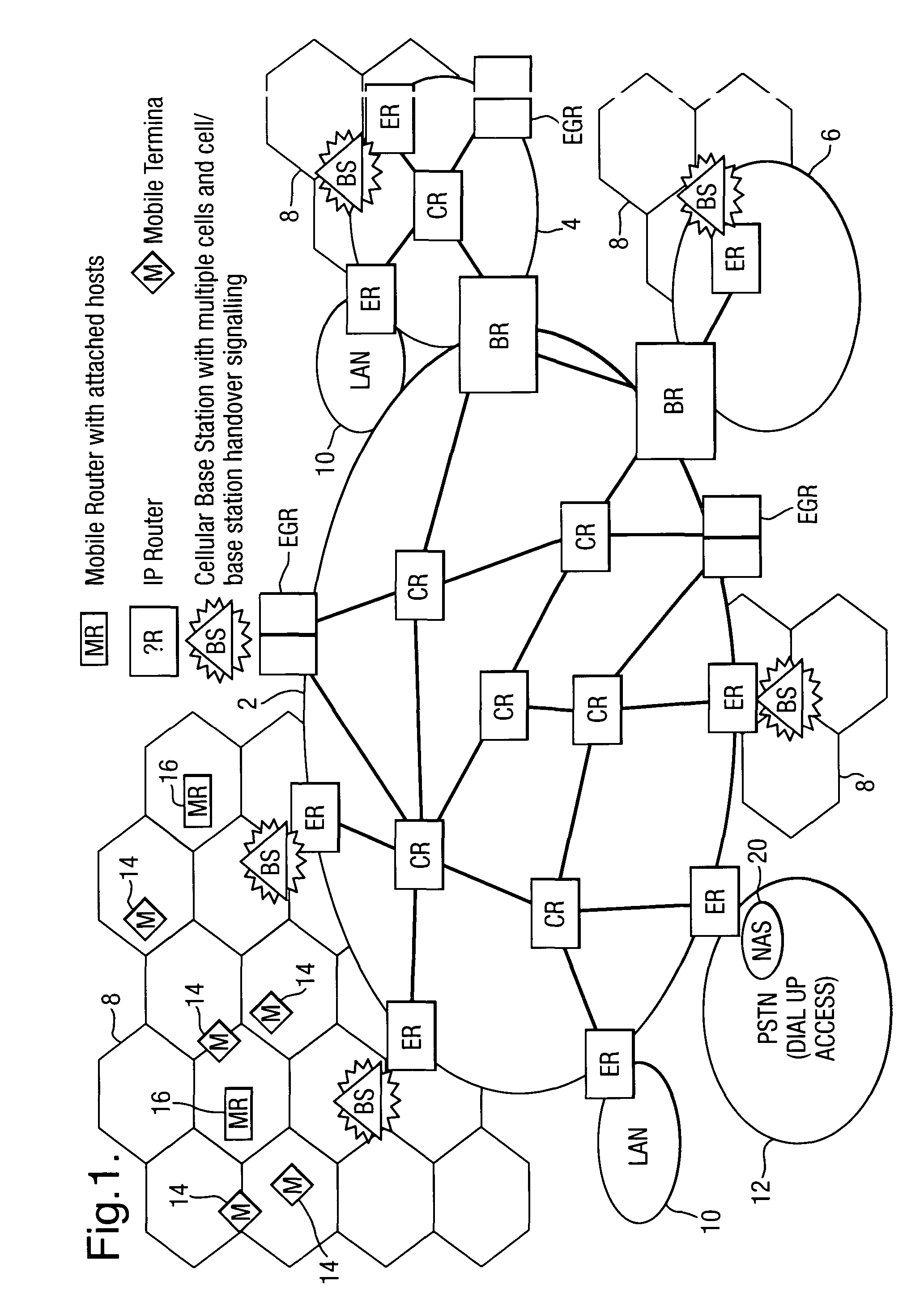
[0031]Referring now to FIG. 1, an example of a fixed / mobile topology in accordance with an embodiment of the present invention is shown. The topology includes, by way of example, three packet switching networks 2, 4, 6 forming an Autonomous System (AS), the extent of which is schematically indicated by dark shading in FIG. 1. One definition given for the term Autonomous System, is “a set of routers and networks under the same administration” (“Routing in the Internet”, Christian Huitema, Prentice-Hall, 1995, page 158). Herein, the term Autonomous System, also referred to as a routing domain in the art, is also intended to mean a network, or a set of networks, having routers running the same routing protocol. An Autonomous System may be connected to other Autonomous Systems forming a global internetwork such as the Internet (used by way of example hereinafter). The routing protocol is an interior gateway protocol, and communications with other Autonomous Systems are achieved via exte...


PUM


Abstract

Routing of packets is controlled in a communications network including an infrastructure of packet switching nodes interconnected by packet transport links, and a plurality of access nodes to which a routing path, defined by data held in packet switching nodes located along the routing path, may be directed in the infrastructure for a given network address.

Description

[0001]This application is the US national phase of international application PCT / GB01 / 04750 filed 26 Oct. 2001 which designated the U.S.RELATED APPLICATIONS[0002]This application is related to the following co-pending commonly assigned applications:[0003]Ser. No.FiledTitleInventors10 / 018,485Dec. 19, 2001TelecommunicationsO'Neill & CorsonRouting10 / 018,486Dec. 19, 2001TelecommunicationsO'Neill & CorsonRouting10 / 018,488Dec. 19, 2001TelecommunicationsO'Neill & CorsonRouting10 / 204,213Apr. 11, 2003TelecommunicationsCorson & O'NeillRouting10 / 381,939Mar. 31, 2003TelecommunicationsO'Neill & CorsonRouting10 / 398,240Apr. 3, 2003TelecommunicationsO'Neill & CorsonRouting10 / 468,236Aug. 18, 2003CommunicationsCorson & O'NeillNetwork10 / 468,351Aug. 18, 2003CommunicationsO'Neill & CorsonNetworkBACKGROUND[0004]1. Technical Field[0005]This invention relates to the routing of telecommunications signals, in particular the routing of packet-based communications such as those used in the “Internet” using the...

Claims


Application Information

Patent Timeline
Patent Type & Authority Patents(United States)
IPC IPC(8): H04J3/24H04L12/56H04L29/06
CPCH04W8/087H04W36/0011H04W40/248H04W40/28H04W40/30H04W40/36H04W80/04
Inventor O'NEILL, ALAN WCORSON, MATHEW S
Owner BRITISH TELECOMM PLC
Why Eureka
Try Eureka