System and method for carrier identification in a pneumatic tube system

a pneumatic tube and carrier identification technology, applied in the field of pneumatic tube carrier systems, can solve the problems of system misdirecting a given carrier, adversely affecting the handling of numerous carriers,

Active Publication Date: 2007-07-10
TRANSLOGIC
View PDF43 Cites 54 Cited by
  • Summary
  • Abstract
  • Description
  • Claims
  • Application Information

AI Technical Summary

Benefits of technology

[0010]As mentioned above, the communications devices are positionable at various locations throughout the system. These locations may include origination / destination stations as well as intermediate locations (i.e., between origination and destination locations). For instance, system routing controllers, e.g., transfer stations, transfer control units (TCUs), and multi-linear transport units (MTUs) as well as the system's pneumatic tubes may incorporate one or more communications devices. Positioning the communications devices at various locations throughout the system provides for monitoring, or tracking, the actual location of carriers as they proceed through the system. Such functionality facilitates a number of system capabilities. For instance, such information (e.g., tracking information) can be used by central controller to address issues that may arise through unforeseen conditions in the system, such as the presence of a “floater”.
[0012]In one aspect of the present invention, the communication devices and identification devices allow for maintaining a predetermined inventory of carriers at different locations throughout the system. In this regard, records stored accessible by the central controller may include inventory records for each station and / or carrier within the system. Each time a carrier is dispatched and / or received by a station, a data entry associated with the quantity of available carriers for such that station may be updated. Likewise, the identity of the carrier received / dispatched may be cross-checked with the inventory records. In this regard, if a user physically transports a carrier between stations, the inventory records of both stations may be accurately adjusted to indicate their actual inventory. That is, the inventory of the station from which the carrier was removed may be adjusted even though the carrier was dispatched from another station.
[0014]In conjunction with providing inventory control of the carriers, the system may be operative to provide various user prompts / messages to the user stations in order to maintain desired inventories. For instance, a station having an excess number of carriers may receive a message or prompt requesting that an empty carrier be returned to the system for redistribution. As will be appreciated, the present aspect allows for maintaining a predetermined inventory of carriers at each user station without necessitating that each carrier be assigned to a particular station.
[0027]As will be appreciated, use of a graphical representation of the pneumatic carrier system may further allow for providing a visual indication of the current status of one or more systems within the system. For instance, if a portion of the system is offline or otherwise inactive, appropriate representation may be provided on the graphical representation. Furthermore, such a graphical representation may be provided on a user interface that is not associated with a particular destination and / or origination location. That is, such a graphical representation may be provided at a central controller / system administrator location such that overall status of the system may be monitored remotely. As will be appreciated, a graphical user interface may be incorporated in to the present arrangement to allow touch screen control of various system functions.

Problems solved by technology

For example, a system may misdirect a given carrier as a result of equipment error.
That is, the presence of even a single, unaccounted for carrier may severely undermine the accuracy of a number of prediction-based determinations made by an SCC, thereby adversely impacting the handling of numerous carriers.

Method used


Image

  • System and method for carrier identification in a pneumatic tube system
  • System and method for carrier identification in a pneumatic tube system
  • System and method for carrier identification in a pneumatic tube system

Examples


Embodiment Construction

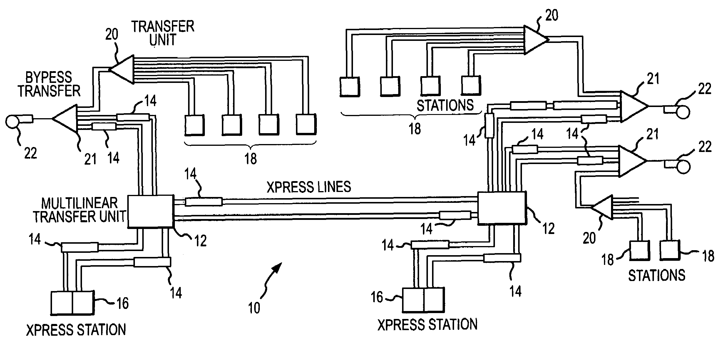
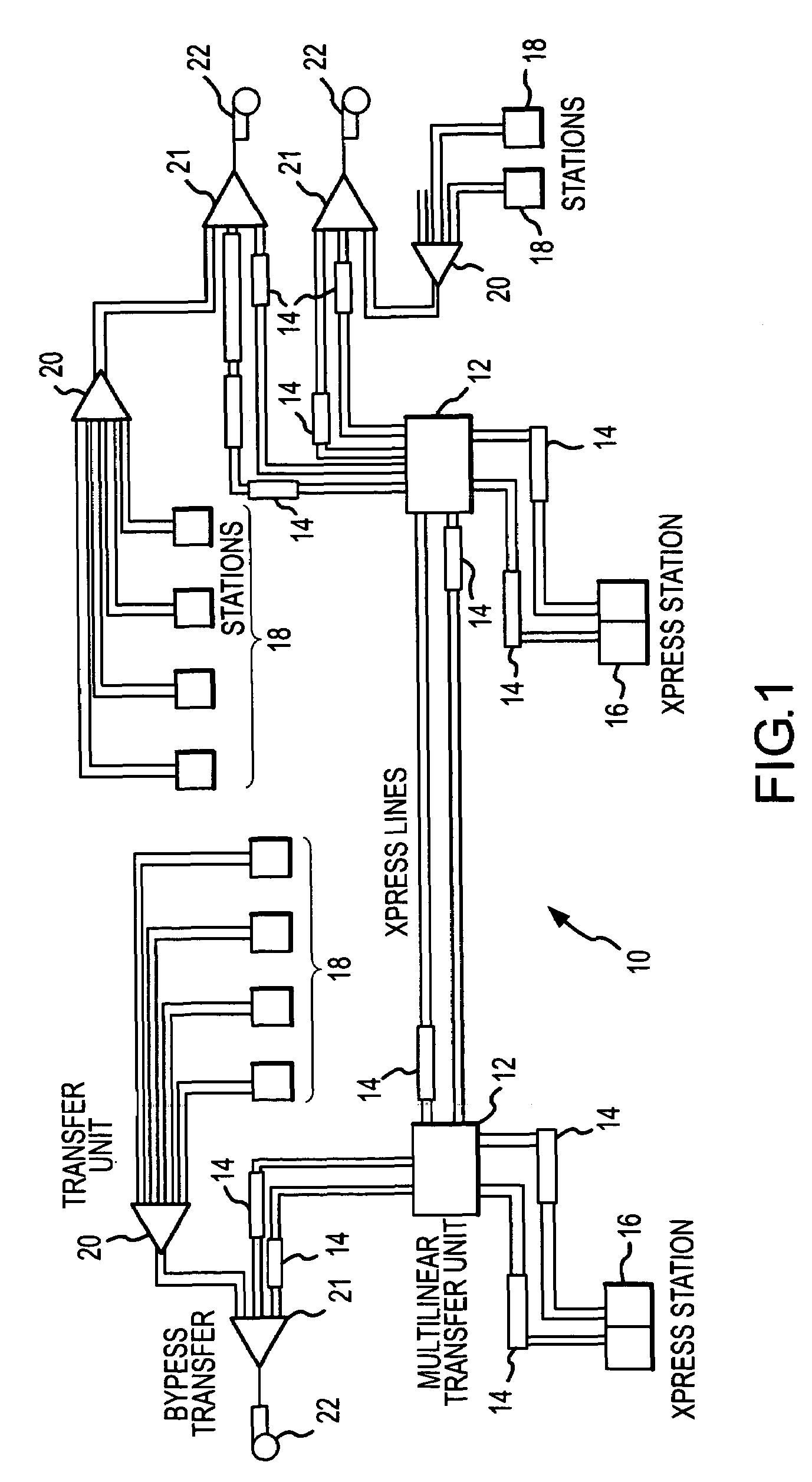
[0044]Disclosed in FIG. 1 is a system diagram for a pneumatic carrier system 10 within which the invention described herein is employable. In general, the pneumatic carrier system 10 transport pneumatic carriers between various user stations 16, 18, each such transport operation being referred to herein as a “transaction”. At each of the user stations 16, 18, a user may insert a carrier, select / enter a destination address / identification and a transaction priority, and then send the carrier. The system determines an optimum path to route the carrier and begins directing the carrier through the system.

[0045]Interconnected with each station 16, 18 is a transfer unit 20 which orders carriers arriving through different tubes from a different stations 16, 18 into a single pneumatic tube. This pneumatic tube is further in connection with a vacuum by-pass transfer unit 21 (i.e., turn around transfer unit) and a blower 22 that provides the driving pneumatic force for container movement. A se...


PUM


Abstract

A system and method provides for the identification and monitoring of carriers within a pneumatic carrier system. Each carrier which is to be employed within the system includes an identification device such as a radio frequency identification (RFID) chip which has stored thereon identification information for the carrier. Positioned throughout the system are communications devices such as antennas and readers which are employed to read and / or write identification information on the chip. When a carrier is put in the system, a destination location can be associated with the particular carrier ID. This associated information is then employed to, among many things, monitor and confirm identity of the carrier as it moves to its destination.

Description

CROSS REFERENCE TO RELATED APPLICATIONS[0001]This application claims priority under 35 U.S.C. §119 to U.S. Provisional Application No. 60 / 556,819 entitled: “SYSTEM AND METHOD FOR CARRIER IDENTIFICATION IN A PNEUMATIC TUBE SYSTEM,” and having a filing date of Mar. 27, 2004, the contents of which are incorporated herein by reference.FIELD OF THE INVENTION[0002]The present invention relates generally to the field of pneumatic tube carrier systems, and more particularly to a system and method for improved carrier handling in a pneumatic tube carrier system employing carrier identification carrier monitoring technology such as radio frequency identification (RFID).BACKGROUND OF THE INVENTION[0003]Pneumatic tube carrier systems are a well-known means for the automated transport of materials between a multitude of locations, any of which may be the origination location or destination location of a transport carrier. A typical system includes a number of pneumatic tubes interconnected in a ...

Claims


Application Information

Patent Timeline
Patent Type & Authority Patents(United States)
IPC IPC(8): G06F7/00
CPCB65G51/44G05B11/44B65G2203/046B65G51/42
Inventor HOGANSON, KENNETH MICHAELCHANEY, GREGORY RICHARDHINNEN, BENNETT CHARLES
Owner TRANSLOGIC
Why Eureka
Try Eureka