Crown reinforcement for a radial tire

a technology of crown reinforcement and radial tires, which is applied in the direction of special tyres, wheels, vehicle components, etc., can solve the problems of crown reinforcement appearance and propagation cracks at said ends, greatly impaired durability of crown reinforcement, and inability to provide a completely satisfactory solution. , to achieve the effect of improving the resistance of the crown structur

Active Publication Date: 2007-07-17
MICHELIN RECH & TECH SA
View PDF4 Cites 20 Cited by
  • Summary
  • Abstract
  • Description
  • Claims
  • Application Information

AI Technical Summary

Benefits of technology

[0029]The combination of the layers of rubber mixes P and G by the selection of their respective elasticity modules MP and MG permit an improvement in the resistance of the crown structure to separation between the ends of the working plies. The presence of these layers of rubber mix in fact seems to make it possible, owing to the decoupling of the plies thus obtained, to protect the end of the narrowest ply and thus prevent or at the very least delay the appearance of delamination of said end of the axially narrowest ply.
[0041]Preferably, when the crown reinforcement of the tire according to the invention comprises a protective ply the end of which is axially between the ends of two working plies, the axially inner end of the first profiled element of rubber mix P is located at a distance from the equatorial plane at least equal to half the width of the axially least wide working ply. Such an embodiment makes it possible to retain decoupling of the end of the axially narrowest working ply and of the axially widest working ply merely by the presence of the second profiled element of rubber mix G. The presence of the protective crown ply may in fact necessitate not interposing the two profiled elements of rubber mix P and G radially between the two working plies in order to avoid an overall thickness of the tire which would be unacceptable in this zone.
[0044]The tests performed according to this variant embodiment of the invention have shown that the presence of such a radially inner layer of rubber mix B adjacent to the radially innermost ply, and more particularly when said ply is axially widest, improves still further the resistance of the crown structure to separation between the ends of the plies of reinforcement elements. It would seem that the presence of this layer of rubber mix B limits the propagation of cracks which may appear in the rubber mass in the vicinity of the ends of the crown plies.

Problems solved by technology

All the conditions under which such a tire is required to travel without doubt make it possible to increase the number of kilometers traveled, the wear of the tire being less; on the other hand, the endurance of the latter, and in particular of the crown reinforcement, is greatly impaired.
The stresses existing at the level of the crown reinforcement, and more particularly the shearing stresses between the crown plies, combined with a non-negligible increase in the operating temperature at the ends of the axially shortest working ply, result in the appearance and propagation of cracks in the rubber at said ends, despite the presence of a thickened layer of rubber at the junction of the edges of the working crown plies.
The same problem exists in the case of edges of two plies having reinforcement elements, said other ply not necessarily being radially adjacent to the first.
It was noted that the various structures listed above did not provide a completely satisfactory solution under conditions of travel which are highly disadvantageous to the tire.

Method used


Image

  • Crown reinforcement for a radial tire
  • Crown reinforcement for a radial tire
  • Crown reinforcement for a radial tire

Examples


Embodiment Construction

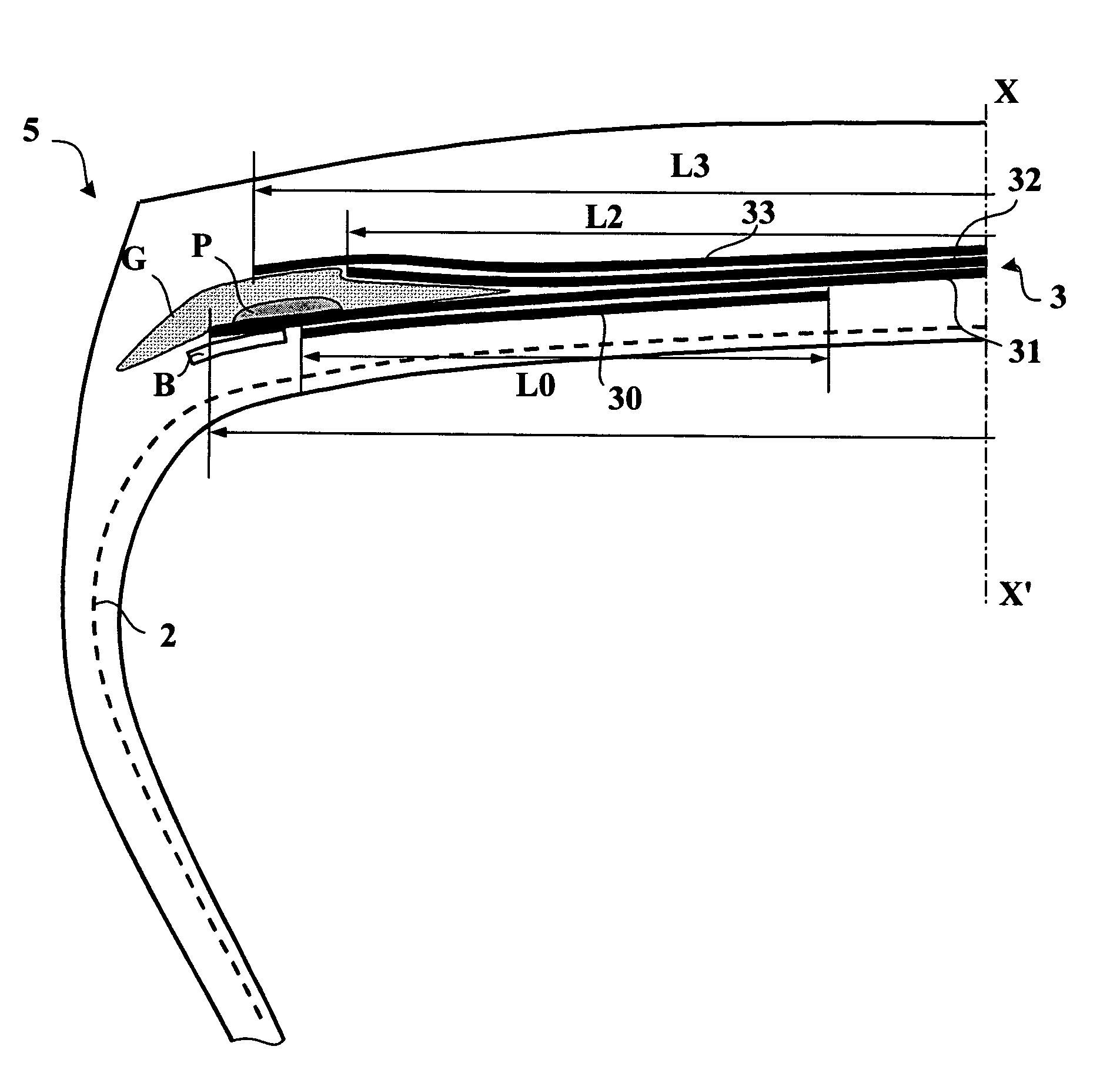
[0055]FIG. 1 shows a partial diagrammatic view in meridian section of a tire 1 of dimension 315 / 80.R.22.5 X. The tire 1 has a form ratio H / S substantially equal to 0.65, H being the height of the tire on its rim and S the maximum axial width of said tire mounted on its 9.00×22.5 operating rim and inflated to a recommended pressure of 9 bar.

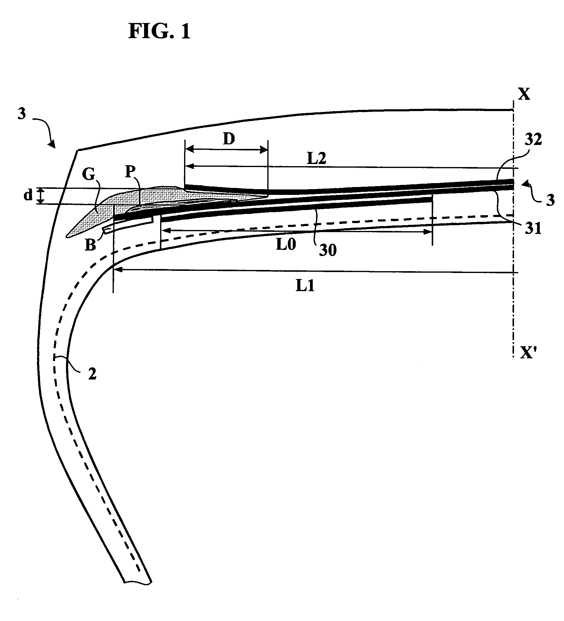
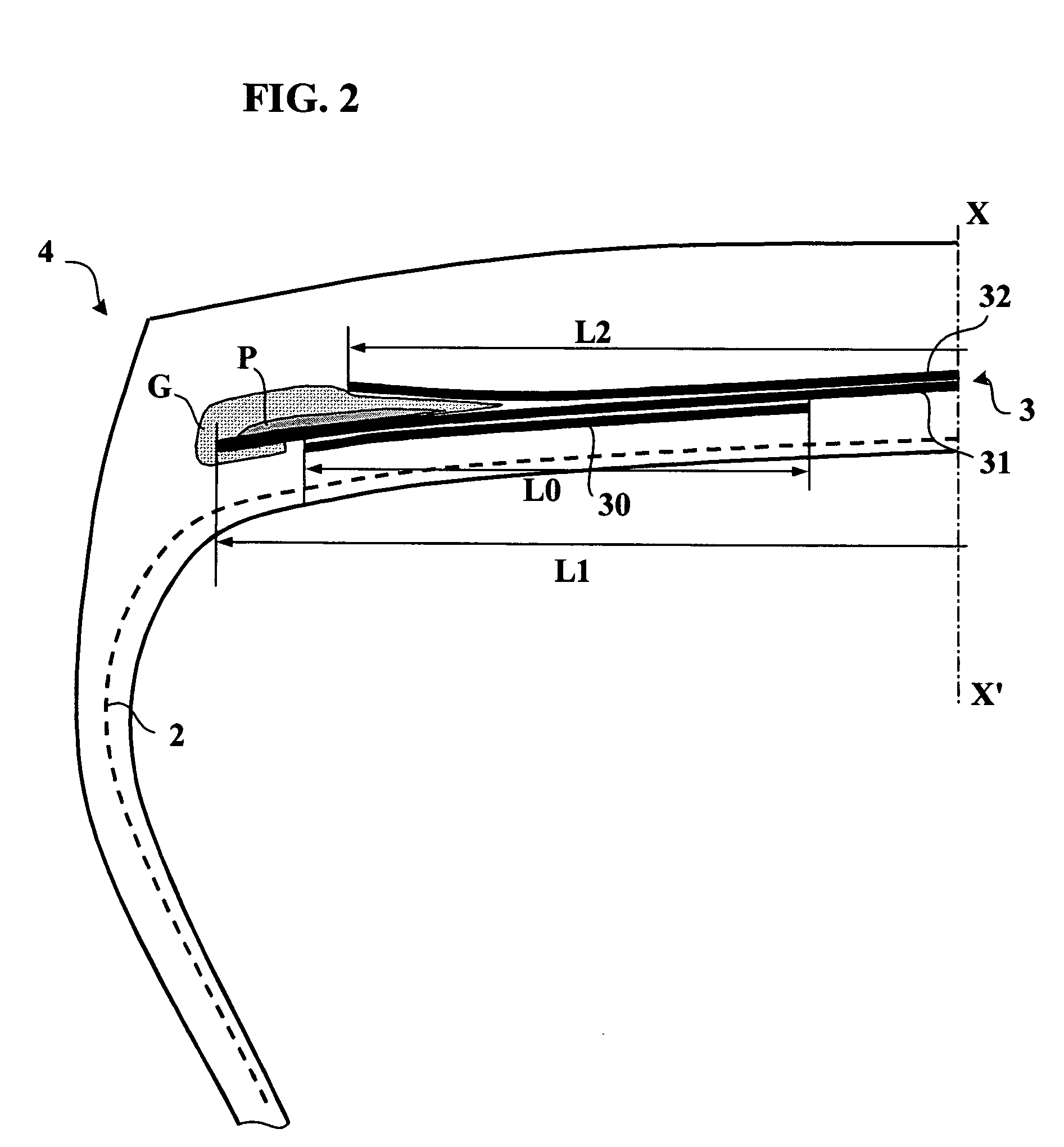
[0056]FIGS. 1 to 3 show only a half-view of the tires which are extended symmetrically relative to the axis XX′, which represents the circumferential median plane, or equatorial plane, of a tire.

[0057]The tire 1 comprises a radial carcass reinforcement composed of a single ply 2 of inextensible metal cables, that is to say, cables which have an elongation of at most 0.2% under a tensile force equal to 10% of the breaking load. Said carcass reinforcement is anchored within each bead; said beads are not shown in FIGS. 1 to 3. It is surmounted, radially to the outside, by a crown reinforcement 3 comprising radially from the inside to the outside:[005...


PUM


Abstract

The invention relates to a tire in which at least one first profiled element P of rubber mix separates the axially widest ply of reinforcement elements from at least one end of a second ply, axially narrower than the axially widest ply, the axially outer end of said first profiled element P being located at a distance from the equatorial plane of the tire which is less than the distance between said plane and the end of the axially widest ply of reinforcement elements, said profiled element P being radially separated at least in part from the liner C of said axially narrower ply of reinforcement elements by a second profiled element of rubber mix G, and said first and second profiled elements of rubber mix P and G and said liner C having secant modules of elasticity under tension at 10% elongation MP, MG, MC respectively such that MC≧MG>MP.

Description

[0001]This application is a U.S. Continuation Application under 35 USC 371 of International Application PCT / EP2004 / 001362 filed Feb. 13, 2004.BACKGROUND OF THE INVENTION[0002]The present invention relates to a tire having a radial carcass reinforcement, and more particularly to a tire intended to be fitted on vehicles bearing heavy loads and traveling at sustained speed, such as, for example, lorries, tractors, trailers or highway buses.[0003]Generally, the carcass reinforcement is anchored on either side in the zone of the bead and is radially surmounted by a crown reinforcement formed of at least two plies, which are superposed and formed of cords or cables which are parallel within each ply. It also generally comprises a ply of metal wires or cables of low extensibility which form an angle of between 45° and 90° with the circumferential direction, this ply, referred to as a triangulation ply, being radially located between the carcass reinforcement and the first, so-called workin...

Claims


Application Information

Patent Timeline
Patent Type & Authority Patents(United States)
IPC IPC(8): B60C9/18B60C9/20
CPCB60C9/18B60C9/2006Y10T152/1081B60C2009/1842
Inventor GERVAIS, PHILIPPEBONDU, LUCIEN
Owner MICHELIN RECH & TECH SA
Why Eureka
Try Eureka