Earth moving machine

a technology of earth moving machine and steering wheel, which is applied in the direction of steering control, steering parts, steering controls, etc., can solve the problems of the risk of accidentally starting the vehicle, and the sway of the arm, so as to avoid accidental operation of the rear working device and avoid accidental operation of the vehicle driving means

Inactive Publication Date: 2007-07-17
KOMATSU UTILITY EURO
View PDF10 Cites 14 Cited by
  • Summary
  • Abstract
  • Description
  • Claims
  • Application Information

AI Technical Summary

Benefits of technology

[0012]In particular, the technical need of the present invention is to provide an earth moving machine which allows accidental operation of the rear working device to be avoided.
[0013]Another technical need of the present invention is to provide an earth moving machine which also allows accidental operation of the vehicle driving means to be avoided.

Problems solved by technology

However, these known technologies have the significant disadvantage of the risk that the rear working device may be operated accidentally, in particular as the operator moves from the front position to the rear position.
When this occurs the arm may swivel and strike any obstacles and / or persons present close to the machine.
Another disadvantage of the machines used today is the similar risk of accidentally starting the vehicle when the operator is working with the rear arm.

Method used


Image

  • Earth moving machine
  • Earth moving machine
  • Earth moving machine

Examples


Embodiment Construction

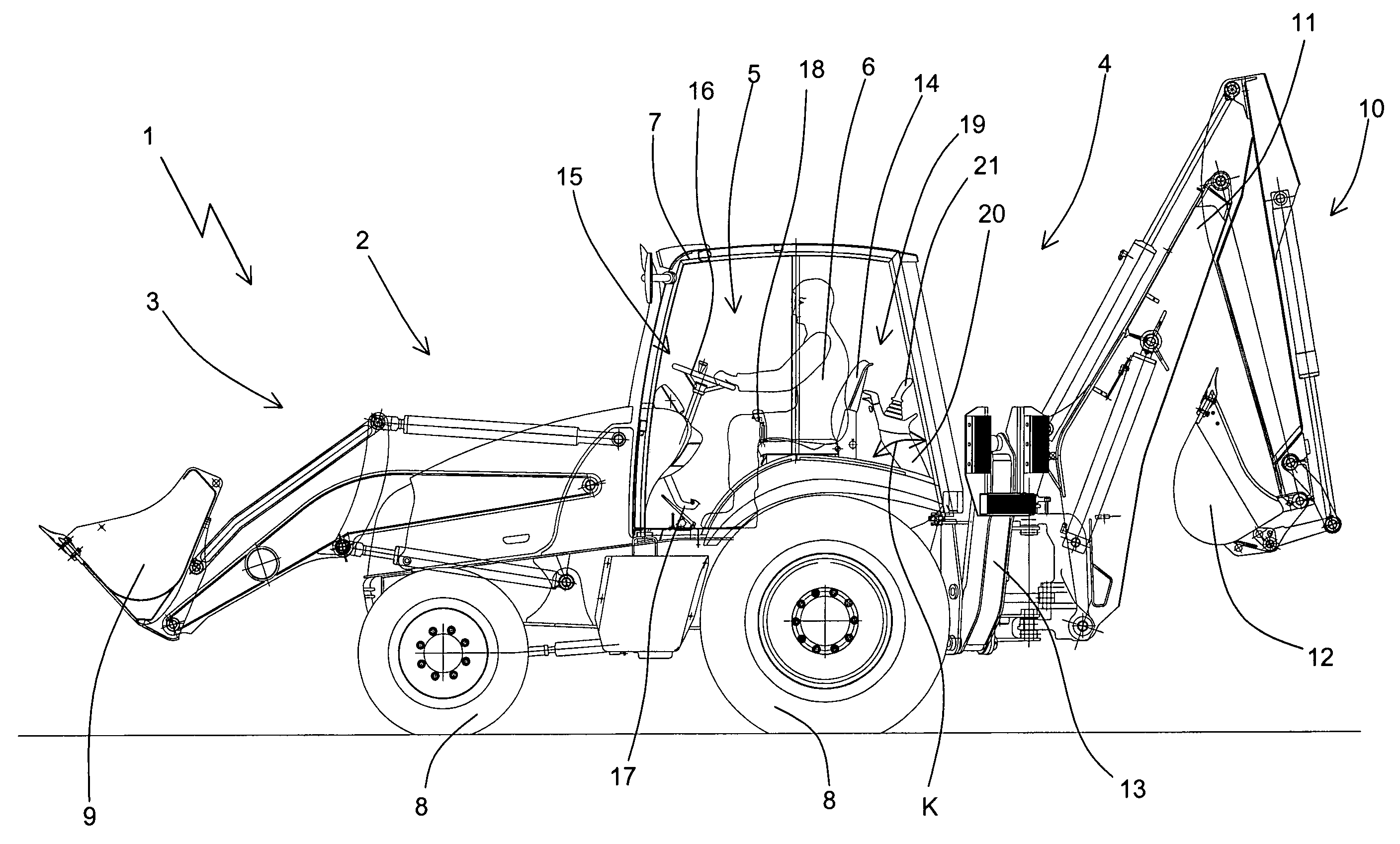
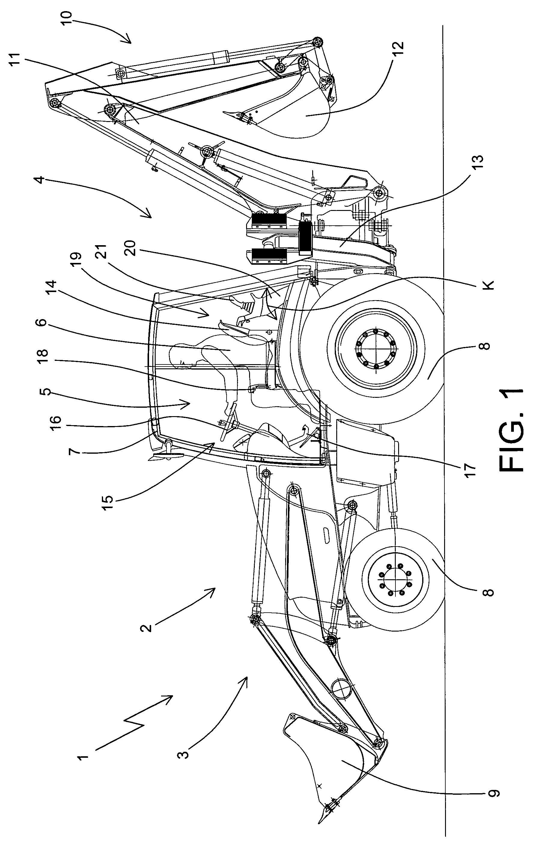
[0024]With reference to the accompanying drawings, the numeral 1 denotes as a whole an earth moving machine made in accordance with the present invention.

[0025]FIG. 1 illustrates a machine 1 comprising a vehicle 2 with a front part 3 and a rear part 4 and which has a manoeuvring position 5 for an operator 6, surrounded by a cab 7 (in other embodiments there may be a canopy in place of the cab 7).

[0026]The vehicle 2 in FIG. 1 also has wheels 8, a front loading shovel 9 and a working device 10 mounted on its rear part 4, and consisting of an articulated arm 11 with a bucket 12.

[0027]Two conventional stabilising feet 13 are also attached to the rear part 4 of the vehicle 2.

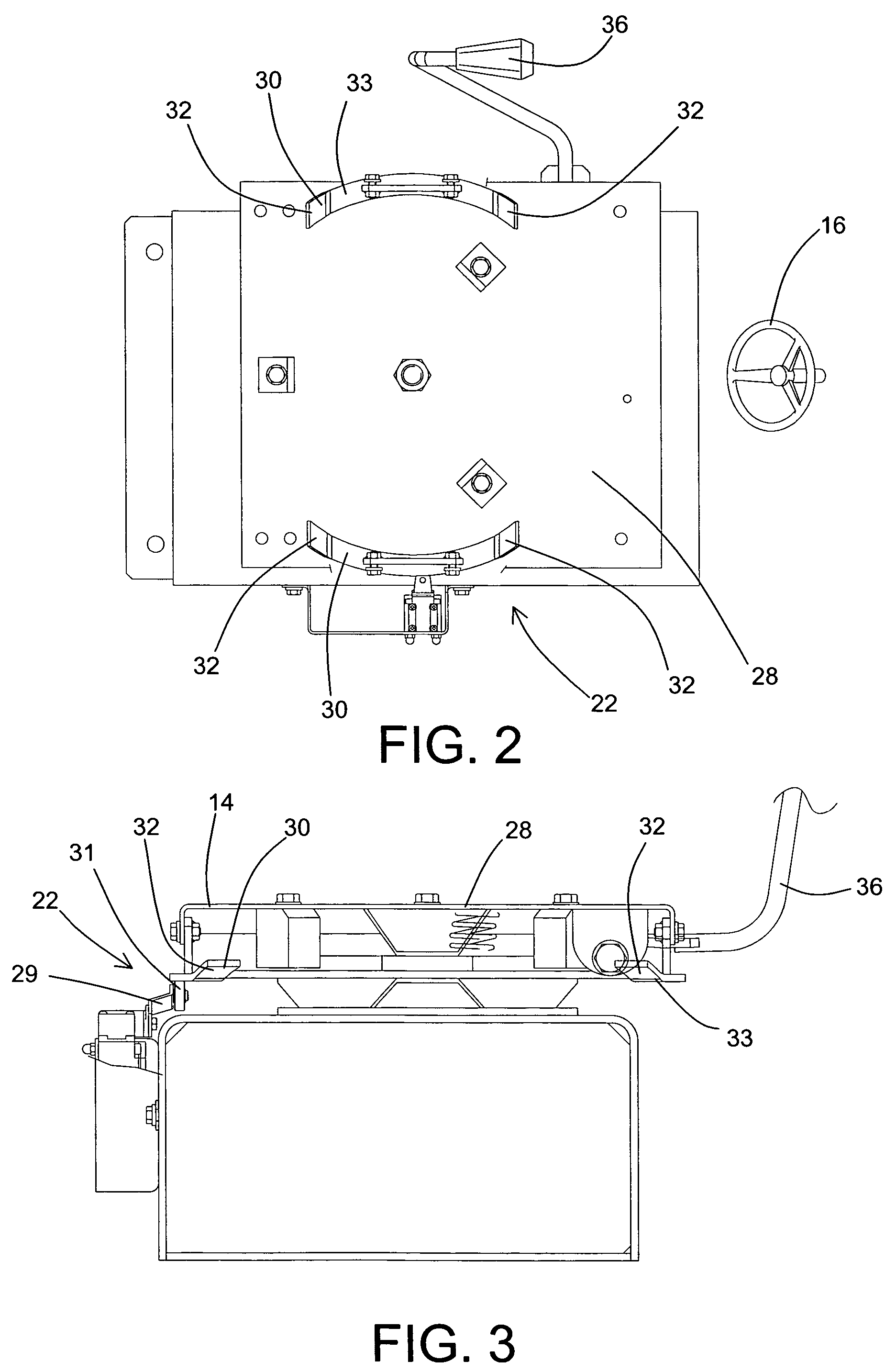
[0028]A seat 14 is rotatably attached to the vehicle 2, according to a vertical axis of rotation, at the manoeuvring position 5.

[0029]Said seat 14 can rotate between a front position in which it faces the front part 3 of the vehicle 2 (FIG. 1) and a rear position in which it faces the rear part 4 of the vehicle 2 (no...


PUM


Abstract

An earth moving machine comprises a vehicle (2), a working device (10) mounted on the rear part (4) of the vehicle (2), a seat (14) rotatably attached to the vehicle (2) and able to rotate between a front position in which it is facing the front part (3) of the vehicle (2) and a rear position in which it is facing the rear part (4) of the vehicle (2), driving means (15) for the vehicle (2), and means (19) for moving the working device (10). The machine (1) also comprises a sensor (22) attached to the seat (14) to detect its position and enabling means operatively connected to the sensor (22) and to the movement means (19) for enabling operation of the movement means (19) at least when the seat (14) is in the front and rear positions, and for inhibiting operation of the movement means when the seat (14) is in at least one intermediate position between the front and rear positions, thus there being detected, during rotation of the seat (14), at least a front enabling zone (23) and a rear enabling zone (24) in which the movement means (19) are enabled, and at least one side inhibit zone (25) in which operation of the movement means (19) is inhibited.

Description

TECHNICAL FIELD[0001]The present invention relates to an earth moving machine of the type comprising a vehicle with a rear working device.BACKGROUND OF THE INVENTION[0002]At a manoeuvring position the vehicle has a seat, rotating according to a vertical axis of rotation, which can rotate between a front position in which it is facing the front part of the vehicle and a rear position in which it is facing the rear part of the vehicle.[0003]When the seat is in the front position the vehicle driving means are in front of the operator, whilst when the seat is in the rear position the working device movement means are in front of the operator. Various types of movement means are currently used. A first technology uses mechanical controls consisting of a set of levers.[0004]A second technology, described for example in U.S. Pat. No. 6,564,896, instead uses servo-controls which can be operated by means of a pair of controllers mounted on the top of two vertical tower assemblies pivoting at...

Claims


Application Information

Patent Timeline
Patent Type & Authority Patents(United States)
IPC IPC(8): B62D1/22
CPCB60N2/143E02F3/964E02F9/166E02F9/2012
Inventor MURARO, UMBERTO
Owner KOMATSU UTILITY EURO
Why Eureka
Try Eureka