Peroxide linear inflator

a linear inflator and peroxide technology, applied in the field of inflators, can solve the problems of undesired or non-preferred combustion products in greater than desired amounts, certain types of inflators, and increased weight and space requirements, and achieve the effect of easy assembly and low production cos

Inactive Publication Date: 2007-07-17
AUTOMOTIVE SYST LAB
View PDF118 Cites 24 Cited by
  • Summary
  • Abstract
  • Description
  • Claims
  • Application Information

AI Technical Summary

Benefits of technology

[0005]The present invention provides an inflator comprising a housing having an interior and a plurality of gas exit orifices formed across its length. A liquid or thixotropic gas source material is positioned in the housing interior and is enclosed in a pliable, rupturable substantially gas-and-moisture-impermeable container. The gas source is a material (for example, hydrogen peroxide) adapted to undergo decomposition to form at least one gaseous decomposition product comprising an inflation gas. A reactant material is also positioned in the interior of the housing. The reactant material is a material (such as a catalyst) formulated to react with the gas source material to produce decomposition of the gas source material. An enclosure is positioned within the housing to form a cavity between an inner wall of the housing and the enclosure. The reactant material is positioned in the cavity. A plurality of orifices formed through the enclosure enables fluid communication between the interior of the enclosure and the cavity. The container is positioned in the enclosure. A resilient, expandable bladder is also positioned in the enclosure. A propellant is provided within the bladder for generation of combustion gases upon ignition of the propellant, to produce expansion of the bladder. An ignition source is provided for igniting the propellant. Upon ignition of the propellant, combustion gases expand the bladder which forces a portion of the container into the enclosure orifices, thereby stressing and rupturing the portions of the container in the orifices and releasing the hydrogen peroxide to flow through the orifice into the cavity, where it reacts with the catalyst to produce inflation gas. The inflator described herein provides a reliable, compact, inexpensively produced, and easily assembled source of non-toxic inflation gas for inflating elements of an inflatable vehicle occupant restraint system.

Problems solved by technology

However, each of these types of inflators has been subject to certain disadvantages, such as greater than desired weight and space requirements, production of undesired or non-preferred combustion products in greater than desired amounts, and production or emission of gases at a greater than desired temperature.

Method used


Image

  • Peroxide linear inflator
  • Peroxide linear inflator
  • Peroxide linear inflator

Examples


first embodiment

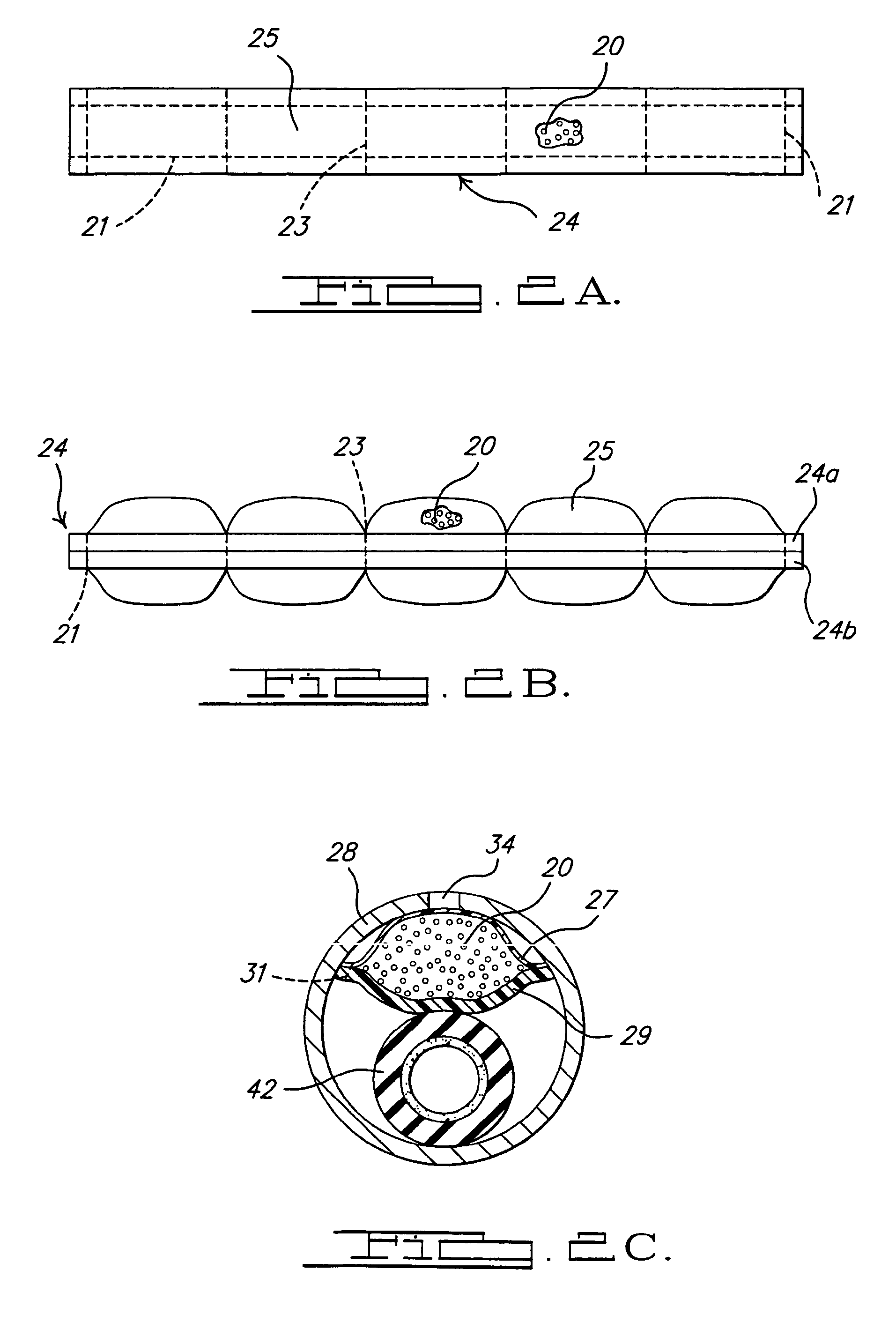
[0027]Referring to FIGS. 2A and 2B, container 24 includes two layers 24a, 24b of film joined along portions thereof (for example, by heat sealing) to provide seams 21 defining one or more hermetically sealed compartments 25 between the layers. In a particular embodiment, each compartment 25 has a substantially equal amount of gas source material 20 provided therein. This facilitates positioning of gas source material 20 substantially uniformly along the extent of inflator 10.

second embodiment

[0028]Referring to FIG. 2C, container 24 includes a film layer 27 in contact with the inside surface of enclosure 28, and a film layer 29, in contact with bladder 42. Film layers 27 and 29 are joined along portions thereof (for example, by heat sealing) to produce one or more hermetically sealed compartments between the layers. Film layers 27 and 29 are designed so that a first predetermined ultimate load F1 is required to produce rupture of film layer 27 and a second predetermined ultimate load F2 is required to produce rupture of layer 29, where second ultimate load F2 is greater than first ultimate load F1. As used herein, the term “ultimate strength” is understood to signify the force necessary to cause rupture of the material.

[0029]In one particular embodiment (shown in FIG. 2C), layer 27 is formed from the same material as layer 29, but layer 29 is thicker (and, therefore, has greater strength) than layer 27. The thickness (and strength) of film layer 27 is such that, when bla...


PUM


Abstract

An inflator includes a housing and a gas source material enclosed in a rupturable container in the housing. The gas source material is adapted to undergo decomposition to form an inflation gas. A reactant material is adapted to react with the gas source material to produce decomposition thereof, and is positioned in a cavity extending between a housing outer wall and an enclosure positioned within the housing. The container and an expandable bladder are positioned in the enclosure. Ignition of a propellant within the bladder generates combustion gases, thereby expanding the bladder. Bladder expansion forces portions of the container into openings formed along the enclosure, thereby stressing and rupturing the portions of the container in the openings and releasing gas source material to flow through the openings into the cavity, where it reacts with the catalyst to produce inflation gas.

Description

CROSS-REFERENCE TO RELATED APPLICATION[0001]This application is entitled to and claims the benefit of Provisional Patent Application Ser. No. 60 / 520,956 filed on Nov. 18, 2003.BACKGROUND OF THE INVENTION[0002]The present invention relates generally to vehicle occupant protection systems, and more particularly to inflators employed in vehicle occupant protection systems incorporating inflatable protection devices.[0003]It is well known to protect a vehicle occupant using an inflatable cushion, or airbag, which is inflated with gas when the vehicle encounters sudden deceleration, such as in a collision. In such systems, the airbag cushion is normally housed in an uninflated and folded condition to minimize space requirements. Upon actuation of the system, the airbag is inflated, in a matter of no more than a few milliseconds, with gas produced or supplied by a device commonly referred to as an inflator.[0004]Many types of inflator devices have been disclosed in the art for the inflati...

Claims


Application Information

Patent Timeline
Patent Type & Authority Patents(United States)
IPC IPC(8): B60R21/26B60R21/272
CPCB60R21/272B60R2021/2725
Inventor STEVENS, BRUCE A.WILLIAMS, GRAYLON K.
Owner AUTOMOTIVE SYST LAB
Why Eureka
Try Eureka