Display panel and display device

a display panel and display device technology, applied in static indicating devices, instruments, solid-state devices, etc., can solve problems such as inability to correct gray level displays

Active Publication Date: 2007-07-17
PIONEER CORP
View PDF14 Cites 190 Cited by
  • Summary
  • Abstract
  • Description
  • Claims
  • Application Information

AI Technical Summary

Benefits of technology

[0012]Accordingly, an object of the present invention is to provide an active type display panel in which light emitting elements such as organic electroluminescence elements are disposed in the form of a matrix and which is capable of implementing a correct gray level display even when used for a long period, and to provide a display device that employs the display panel and a driving method for the display panel.

Problems solved by technology

Therefore, when there is a variation in the drive current characteristic with respect to the input control voltage as a result of a drive transistor temperature variation and inconsistencies in the transistor itself, a correct gray level display is not possible.

Method used


Image

  • Display panel and display device
  • Display panel and display device
  • Display panel and display device

Examples


Embodiment Construction

[0029]The present invention will be described below in more detail with reference to the accompanying drawings in accordance with the embodiments.

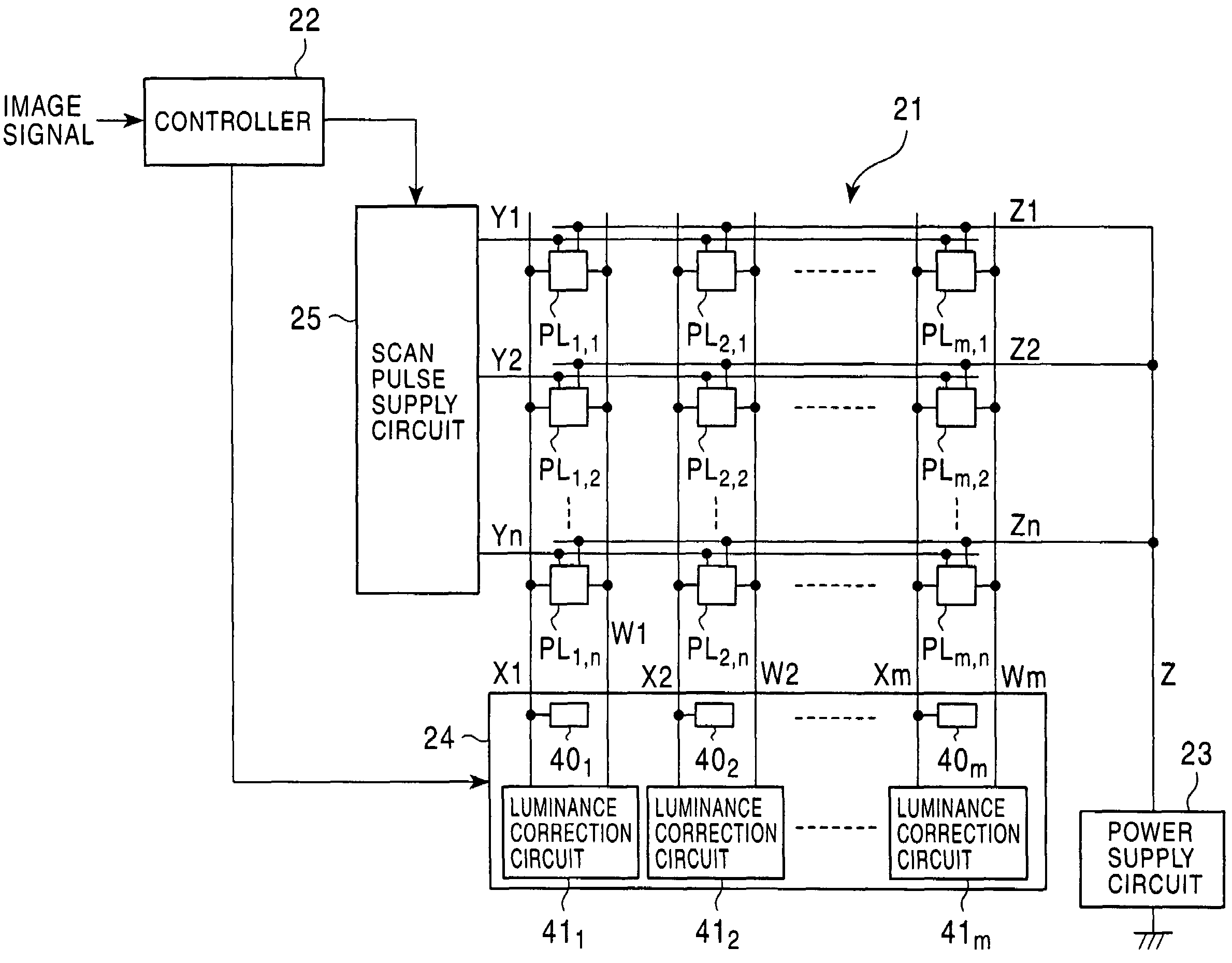
[0030]FIG. 6 shows an EL display device to which the present invention is applied. The display device comprises a display panel 21, a controller 22, a power supply circuit 23, a data signal supply circuit 24, and a scan pulse supply circuit 25.

[0031]The display panel 21 includes a plurality of data lines X1 to Xm which are disposed in parallel (where m is an integer of two or more), a plurality of scan lines Y1 to Yn (where n is an integer of two or more), and a plurality of power supply lines Z1 to Zn. The display panel 21 further includes a plurality of measurement lines W1 to Wm.

[0032]The plurality of data lines X1 to Xm and the plurality of measurement lines W1 to Wm are disposed in parallel as shown in FIG. 6. Likewise, the plurality of scan lines Y1 to Yn and the plurality of power supply lines Z1 to Zn are disposed in parallel as sh...


PUM


Abstract

An active type display panel comprises a plurality of pixel sections each having a series circuit constituted by a light emitting element and a drive element for supplying a drive current to the light emitting element, a pair of power supply lines which connect the series circuits of the pixel sections in parallel, and a plurality of measurement lines. Each of the pixel sections includes a switch element between a point connecting the light emitting element and the drive element, and one line of the measurement lines. A display device, in which the display panel is used, detects the voltage across the terminals of the light emitting element and controls the drive element such that the voltage across these terminals is a predetermined voltage.

Description

BACKGROUND OF THE INVENTION[0001]1. Field of the Invention[0002]The present invention relates to an active type display panel in which light emitting elements such as organic electroluminescence elements are disposed, a display device in which the display panel is used, and a display panel driving method thereof.[0003]2. Description of the Related Art[0004]Electroluminescence display devices (referred to as EL display devices hereinafter) mounted with a display panel employing organic electroluminescence elements (referred to simply as EL elements hereinafter) in the form of light emitting elements carrying pixels are currently attracting attention. Known systems for driving display panels by means of these EL display devices include simple matrix type and active matrix type systems. In comparison with simple matrix type systems, active matrix type EL display devices consume very little electrical power and afford advantages such as low cross-talk between pixels, and are particularl...

Claims


Application Information

Patent Timeline
Patent Type & Authority Patents(United States)
IPC IPC(8): G09G3/30G09G3/32G09G3/10H01L51/50G09G3/20
CPCG09G3/3233G09G3/3283G09G3/3291G09G2300/0842G09G2300/0876G09G2320/029G09G2320/0295G09G2320/043G09G2320/045
Inventor ISHIZUKA, SHINICHI
Owner PIONEER CORP
Why Eureka
Try Eureka