
Method of edge based interpolation

a technology of edge and interpolation, applied in the direction of picture reproducers using projection devices, signal generators with optical-mechanical scanning, television systems, etc., can solve the problems of poor display to the viewer, degrade the resulting frame image, and reduce the vertical resolution of the imag

Inactive Publication Date: 2007-07-17
PANASONIC CORP
View PDF21 Cites 43 Cited by
  • Summary
  • Abstract
  • Description
  • Claims
  • Application Information

AI Technical Summary

Problems solved by technology

Interlaced images exhibit distorting artifacts such as vertical line flicker or loss of vertical detail that degrade the resulting frame image.
For pixels which lie on a diagonal edge, this could result in “jaggies” (a line which appears to be jagged or stair-stepped, rather than smooth).
For pixels which are not on an edge, such duplication could result in pixels that do not correspond to the image being displayed, resulting in a poor display to the viewer.
This method also reduces the vertical resolution of the image compared to an interlace-scan image and may result in areas of the image flickering at a 30 Hz rate.

Method used


Image

  • Method of edge based interpolation
  • Method of edge based interpolation
  • Method of edge based interpolation

Examples


Embodiment Construction

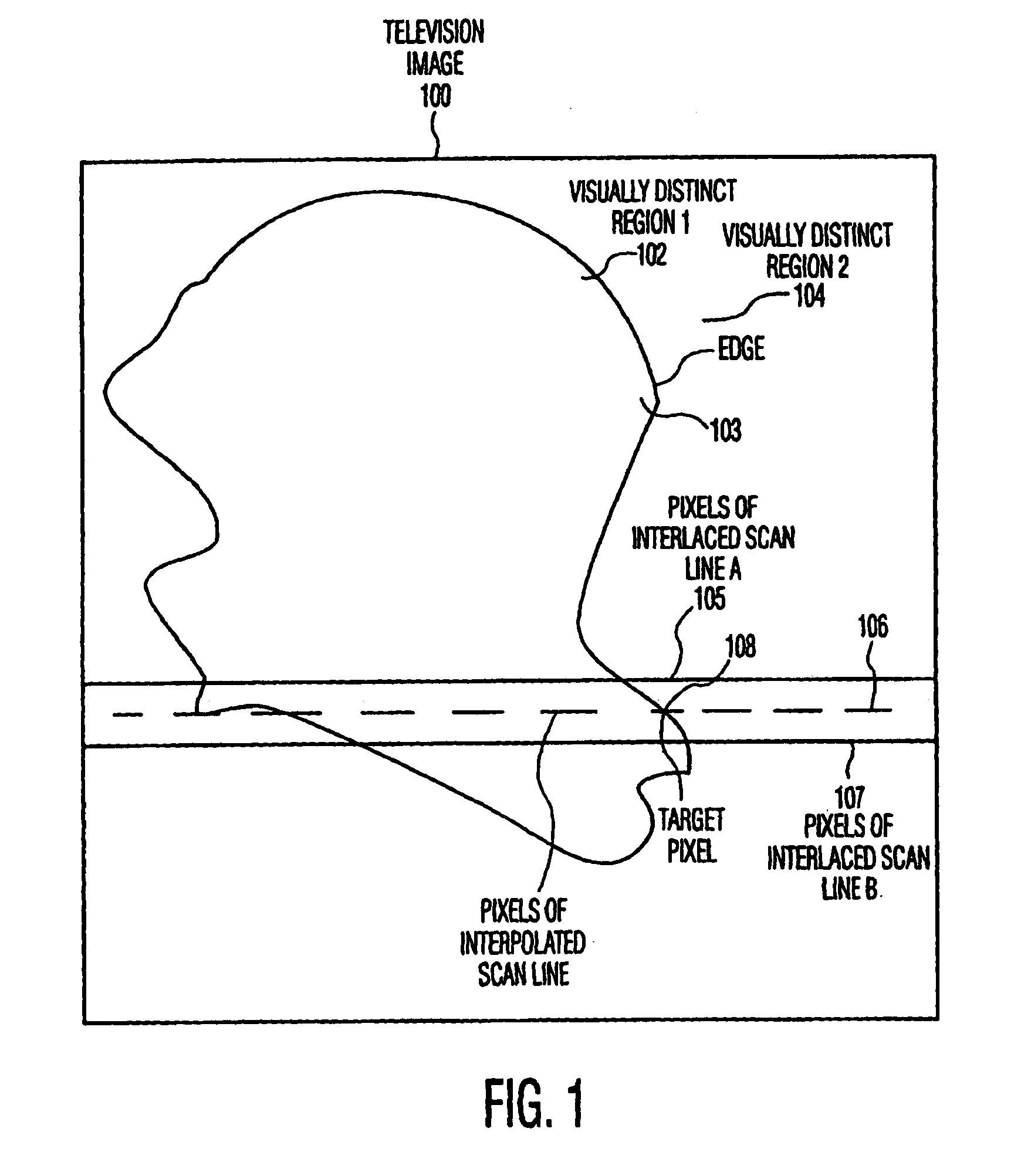
[0019]The present invention relates to a method and apparatus for converting an interlace scan video signal into a progressive scan video signal, and specifically for generating picture elements (pixels) of interstitial lines in an interlaced field image, which pixels lie on an edge between visually distinct regions in the interlaced field.

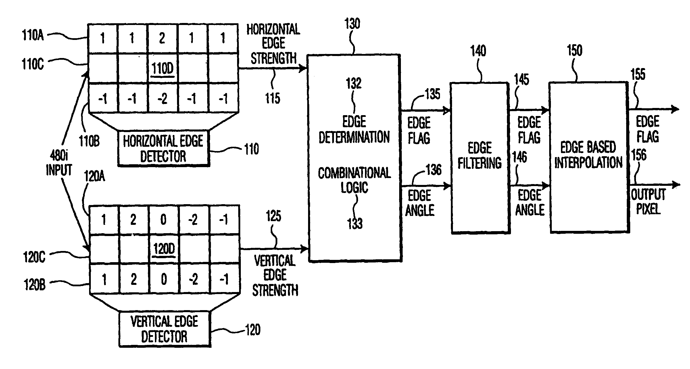
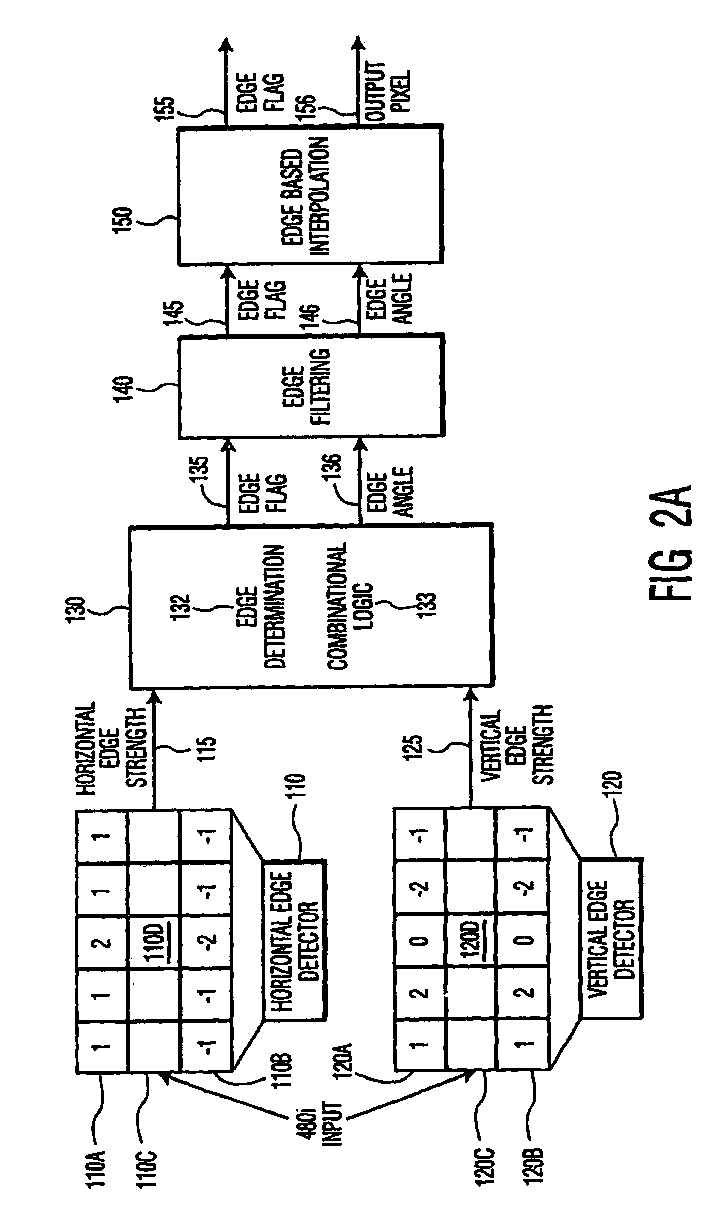
[0020]In an exemplary embodiment of the invention shown in FIG. 2A, an arithmetic approximation technique is used to determine the angle of an edge at a particular pixel position to yield an interpolated pixel well within acceptable tolerance levels, while avoiding overhead of mathematical calculation or memory usage. The arithmetic approximation is achieved using combinatorial logic. The exemplary embodiment of the invention also allows for different degrees of precision in the result.

[0021]The exemplary embodiment uses a horizontal edge detector 110 and a vertical edge detector 120, that are specifically designed for use with interlace-scan vide...


PUM


Abstract

A method for detecting an edge and generating an interpolated edge pixel at a target pixel position between two lines of an interlace scan image first determines gradient intensities in the horizontal and vertical directions and then calculates the angle of the edge by comparing the gradient intensities. The interpolated pixel value is calculated from samples in the interlace scan image that lie along the identified angle and are proximate to the target pixel position. The method represents the gradient strengths and the difference between them as bit strings; locates the most significant non-zero bit in the larger gradient value; divides the value of the corresponding bit position in the difference string, and a predetermined number of following positions, by increasing powers of 2; sums the results; subtracts the sum from 1.0 and uses the inverse tangent function to calculate the angle of the edge.

Description

TECHNICAL FIELD[0001]The present invention relates generally to a method for converting interlace scan video signals to progressive scan video signals and, in particular, to a method of interpolating a value for a picture element (pixel) of an interstitial row of pixels, lying on an edge between visually distinct regions of an interlace scan video image.BACKGROUND OF THE INVENTION[0002]The image on the television screen consists of pixels, arranged horizontally in rows, generally offset vertically by one pixel position from one another. Each pixel is assigned three values, which indicate the respective intensities of the red, green, and blue components of the pixel. A video image is generated by sequentially displaying the rows of pixels as horizontal lines of the image.[0003]Existing analog broadcast standards such as NTSC, PAL and SECAM use two video fields to generate a single video frame. Each field includes one-half of the horizontal lines that make up the image frame. One fiel...

Claims


Application Information

Patent Timeline
IPC IPC(8): H04N11/20H04N7/01H04N5/44
CPCH04N7/012
Inventor ORLICK, CHRISTOPHER J.
Owner PANASONIC CORP
Learn More