System and mehtod for differential phase contrast microscopy

A differential phase contrast and microscopic system technology, applied in the field of microscopic technology, can solve problems such as reduced measurement efficiency and unfavorable production line detection, and achieve the effects of saving measurement time, enhancing resolution, and reducing noise

Active Publication Date: 2019-05-21
骆远
View PDF5 Cites 1 Cited by
  • Summary
  • Abstract
  • Description
  • Claims
  • Application Information

AI Technical Summary

Problems solved by technology

In addition, since the use of semicircular light intensity shielding requires light intensity changes up to twelve axes, the measurement efficiency is also greatly reduced, which is not conducive to detection on the production line

Method used


Image

  • System and mehtod for differential phase contrast microscopy
  • System and mehtod for differential phase contrast microscopy
  • System and mehtod for differential phase contrast microscopy

Examples


Embodiment Construction

[0024] Various exemplary embodiments will be described more fully hereinafter with reference to the accompanying drawings, in which some exemplary embodiments are shown. However, inventive concepts may be embodied in many different forms and should not be construed as limited to the illustrative embodiments set forth herein. Rather, these exemplary embodiments are provided so that this disclosure will be thorough and complete, and will fully convey the scope of the inventive concept to those skilled in the art. Like numbers indicate like components throughout. The differential phase contrast microscopy system and method will be described below with various embodiments and drawings, however, the following embodiments are not intended to limit the present invention.

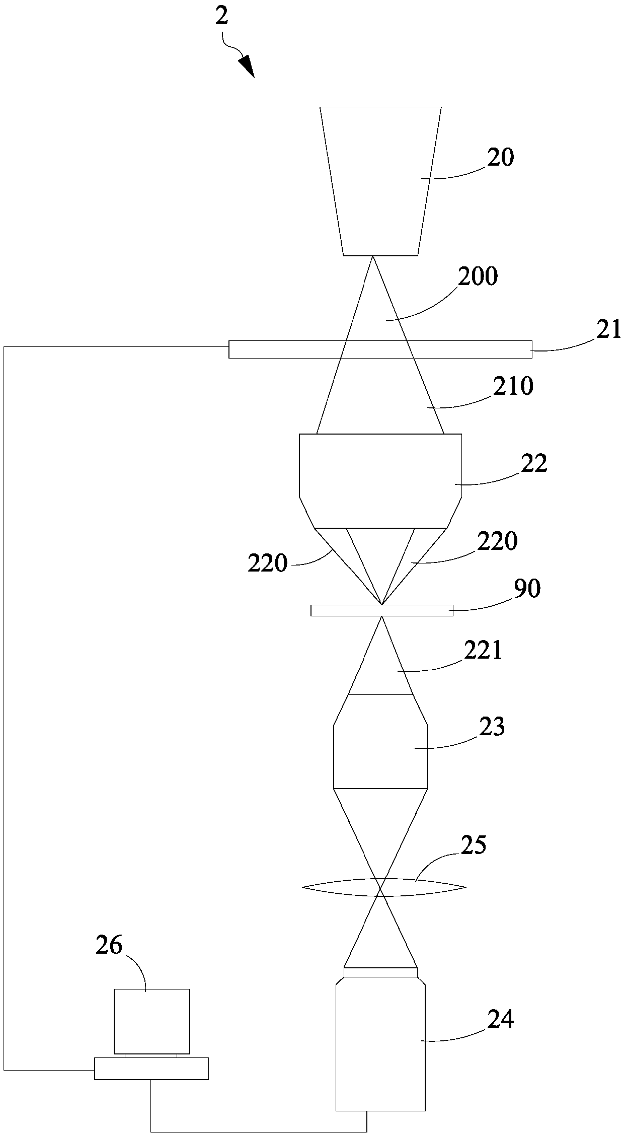
[0025] see figure 2As shown, this figure is a schematic diagram of the optical structure of the differential phase contrast microsystem of the present invention. In this embodiment, the microsystem 2 includes a ...


PUM


Abstract

The invention provides a system and a method for differential phase contrast microscopy. The system comprises a light strength modulating module, a light focusing lens, an objective lens and an imageacquisition module. The light strength modulating module is used for modulating an incident light field to a detecting optical field with gradient strength distribution according to a control signal.The focusing lens is used for receiving the detecting optical field and generates an off-axis optical field for projecting to a to-be-measured object, and furthermore generates the light field of theto-be-measured object for receiving by the objective lens. The image acquisition module is used for receiving the optical field of the to-be-measured object, thereby generating an optical image with corresponding strength gradient distribution. The method further comprises the steps of controlling the light strength modulating module for generating a first gradient shield with gradually reducing light strength in a first axial direction, a second gradient shield with gradually increasing light strength in the first axial direction, a third gradient shield with gradually reducing light strengthin a second axial direction, and a fourth gradient shield with gradually increasing light strength in the second axial direction, and making the image acquisition module to acquire a first optical image, a second optical image, a third optical image and a fourth optical image which respectively correspond with the first gradient shield, the second gradient shield, the third gradient shield and the fourth gradient shield.

Description

technical field [0001] The present invention is a microscopic technique, in particular, a differential method for obtaining four corresponding images of the object to be measured by off-axis illumination using a biaxial light field with a gradient distribution of light intensity for phase measurement. Phase contrast microscopy systems and methods. Background technique [0002] Differential phase contrast microscopy (differential phase contrast, DPC) is a technology that uses non-interference images to analyze the characteristics of objects. Under the condition of phase contrast. Due to the advantage of being label-free, differential phase-contrast microscopy has been widely used in the field of commercial detection to observe biological specimens without photobleaching or phototoxicity. [0003] In the conventional technology, in the field of non-visible light, there is a differential microscopy technique that uses an X-ray source and a grating to generate phase contrast. ...

Claims


Application Information

Patent Timeline
Patent Type & Authority Applications(China)
IPC IPC(8): G01B9/04G01B11/24
Inventor 骆远陈锡勋
Owner 骆远
Why Eureka
Try Eureka