
Clustering method using two-stage local binary pattern and iterative image test system

A test system, binary image technology, applied in the field of super-resolution, can solve storage waste and other problems

Active Publication Date: 2018-04-06
NCKU RES & DEV FOUND +1
View PDF3 Cites 0 Cited by
  • Summary
  • Abstract
  • Description
  • Claims
  • Application Information

AI Technical Summary

Problems solved by technology

However, the traditional region binary map will generate many extremely rare occurrence clusters (e.g., the utilization rate is less than 0.001% of the total), thus resulting in waste of storage

Method used


Image

  • Clustering method using two-stage local binary pattern and iterative image test system
  • Clustering method using two-stage local binary pattern and iterative image test system
  • Clustering method using two-stage local binary pattern and iterative image test system

Examples


Embodiment Construction

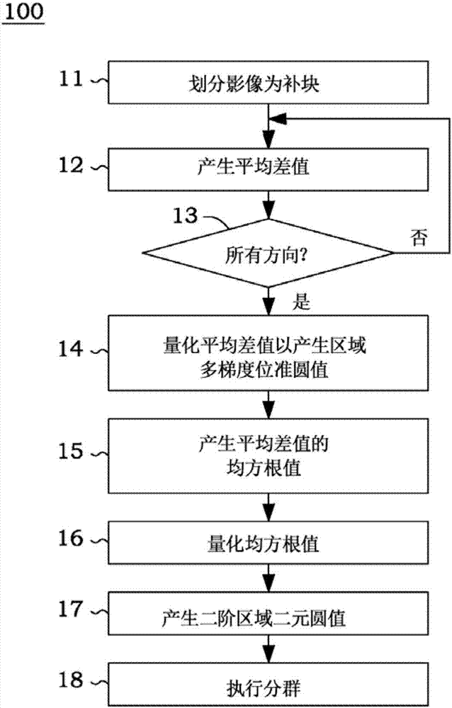
[0055] figure 1 The flow chart of is showing the clustering method 100 using the second-stage local binary pattern (two-stage local binary pattern, 2SLBP) according to the embodiment of the present invention. The clustering method 100 can perform image processing (eg, training and testing) on ​​super-resolution (eg, sample-based super-resolution) image signals. The steps of the clustering method 100 can be implemented by an electronic circuit such as a digital image processor, and the super-resolution image processing can be implemented by using hardware, software or a combination thereof.

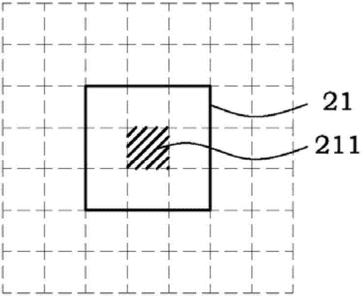
[0056] In step 11, the image to be grouped is divided into patches of a default size (eg, 7x7). Figure 2A Instantiates a patch of size 7x7. Figure 2A Also shown is a central sub-block 21 (eg, 3x3 in size) with a central pixel 211 located in the center of the patch.

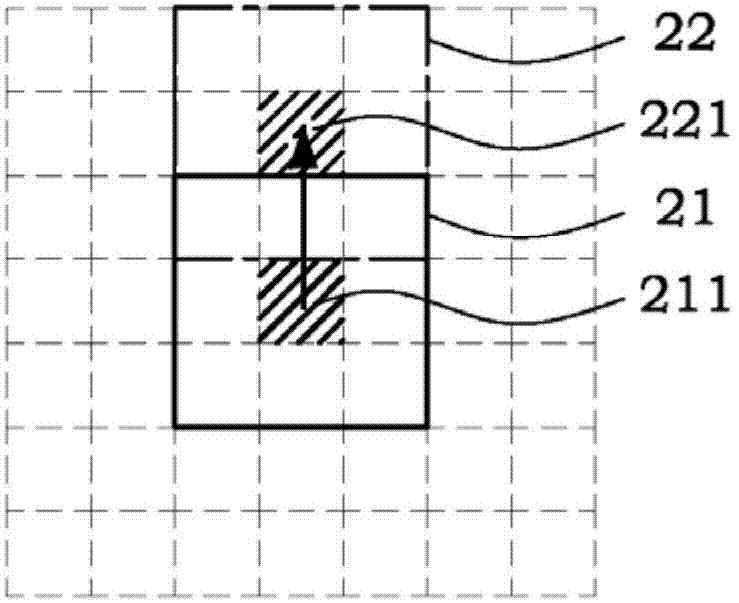
[0057] In step 12, gradient direction values ​​are generated. In one embodiment, the average difference between the ad...


PUM


Abstract

The invention relates to a clustering method using a two-stage local binary pattern (2SLBP). The method comprises the steps of generating a gradient direction value according to a central sub-block and adjacent sub-blocks of each patch of an image; quantizing each gradient direction value to generate a quantized gradient direction value; generating a gradient strength value according to each gradient direction value; quantizing each gradient strength value to generate a quantized gradient strength value; connecting the quantized gradient direction values with the quantized gradient strength values in series to generate a 2SLBP value; and using the 2SLBP value as an pointer to execute the clustering of super-resolution image processing.

Description

technical field [0001] The present invention relates to super-resolution (SR) technology, in particular to a grouping method using a two-stage local binary pattern (2SLBP) and an iterative image testing system. Background technique [0002] High-resolution displays are developing rapidly, however, there are still many image capture devices (eg, surveillance devices) that generate low-resolution images. To fill the gap between the two, super-resolution (SR) techniques are thus proposed. Example-based super resolution (example-based super resolution) is a kind of super-resolution technology, which searches the high-resolution (HR) patch from the patch database, and uses the obtained high-resolution patch to Replaces low-resolution sub-blocks of a low-resolution (LR) input image, thus predicting a high-resolution image. [0003] In this specification, "high resolution" and "low resolution" are relative terms. Therefore, high-resolution imagery has a higher resolution than lo...

Claims


Application Information

Patent Timeline
Patent Type & Authority Applications(China)
IPC IPC(8): H04N17/00
CPCH04N17/00
Inventor 谢明得徐芳凯陈俊维杨得炜
Owner NCKU RES & DEV FOUND
Learn More