Drain and a building structure having a drain

a technology for building structures and drains, which is applied in the direction of artificial water canals, cable-laying vessels, pipe-laying vessels, etc., can solve the problems of requiring great care and skill in the use of drains, main parts of drains to be manufactured from aesthetically less attractive materials, and the drain does not disclose any way of preventing water in the shower room from penetrating, etc., to achieve the effect of simple wet area

Inactive Publication Date: 2007-07-24
UNIDRAIN
View PDF48 Cites 27 Cited by
  • Summary
  • Abstract
  • Description
  • Claims
  • Application Information

AI Technical Summary

Benefits of technology

[0031]The drain according to the first aspect of the present invention thereby defines a trough-shaped fluid tight drain, the objective of the flange part and the parts extending above the flange part being to integrate the drain in a building structure in such a manner that an excellent water sealing may easily be obtained between the walls, floor and drain.
[0033]In a preferred embodiment of the invention, the drain may further be elongated and be provided with two opposed side parts integral with the bottom part and the first part. The sidewalls extend in vertical direction from the bottom part, through and above a plane defined by the flange part. This drain is particularly suitable for use in narrowly confined spaces, such as in a shower bath where the drain extends between two opposed walls delimiting the bathroom and having each a watertight covering that covers the side walls of the drain. This allows the floor to be provided with a unidirectional slope towards the back part of the drain, making it significantly simpler to establish the wet area when comparing to conventional bathrooms.

Problems solved by technology

This known drain does not disclose any way of preventing water in the shower room from penetrating into the wall construction, other than by arranging the drain in a position distant from the wall and then forming the shower room floor with an inclination in front of and behind of the drain such that water may run towards the drain from any location in the shower room.
Accordingly, use of this drain requires great care and skill when laying the floor.
Since this known drain does not allow for the provision of a grating, the upstanding parts and the bottom part must have an aesthetically attractive surface and, accordingly, this known drain does not allow the for the main parts of the drain to be manufactured from aesthetically less attractive materials but rather require that the choice of material and color of the upstanding parts and the bottom part be made in accordance with the appearance of the floor lining.

Method used


Image

  • Drain and a building structure having a drain
  • Drain and a building structure having a drain
  • Drain and a building structure having a drain

Examples


Embodiment Construction

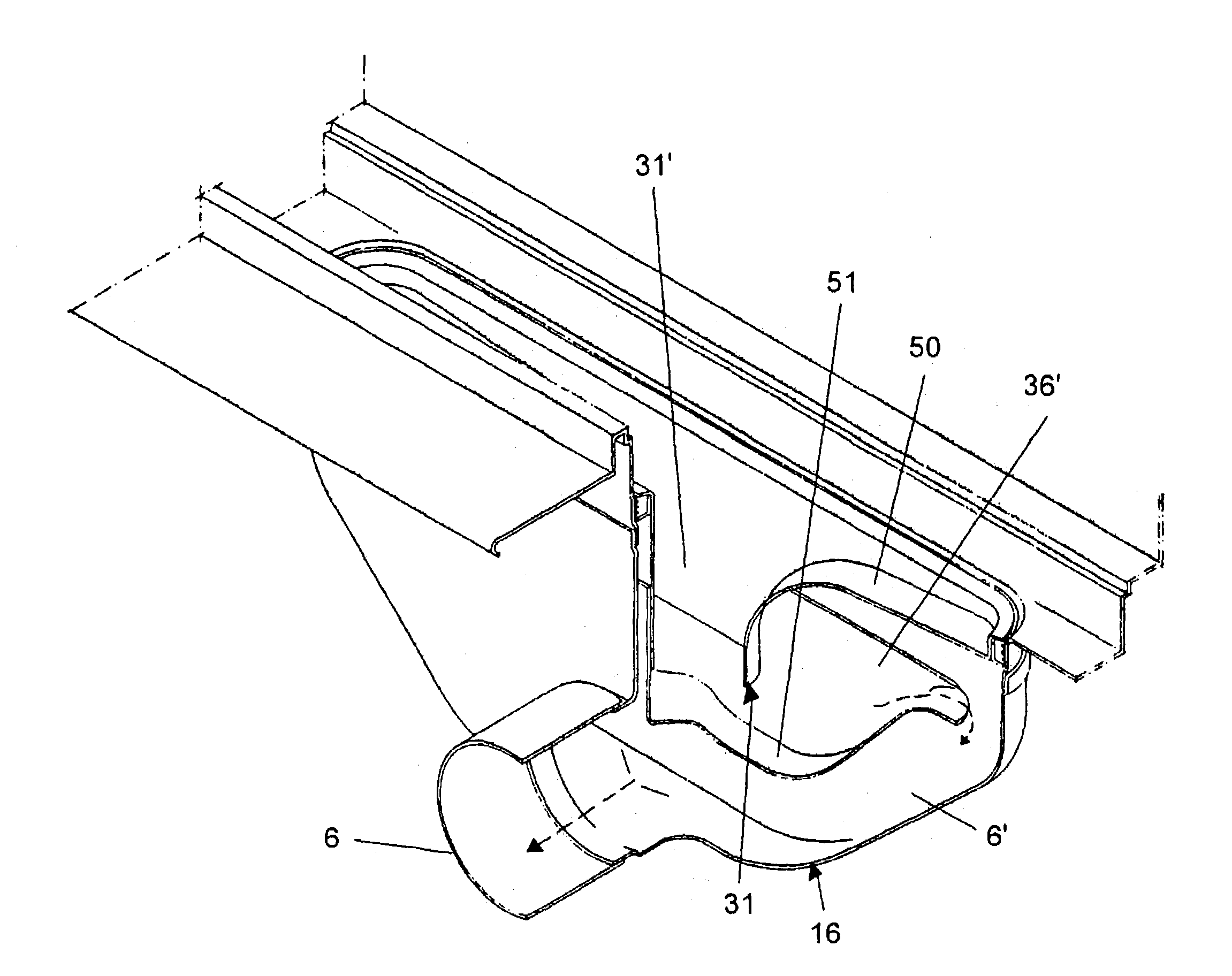
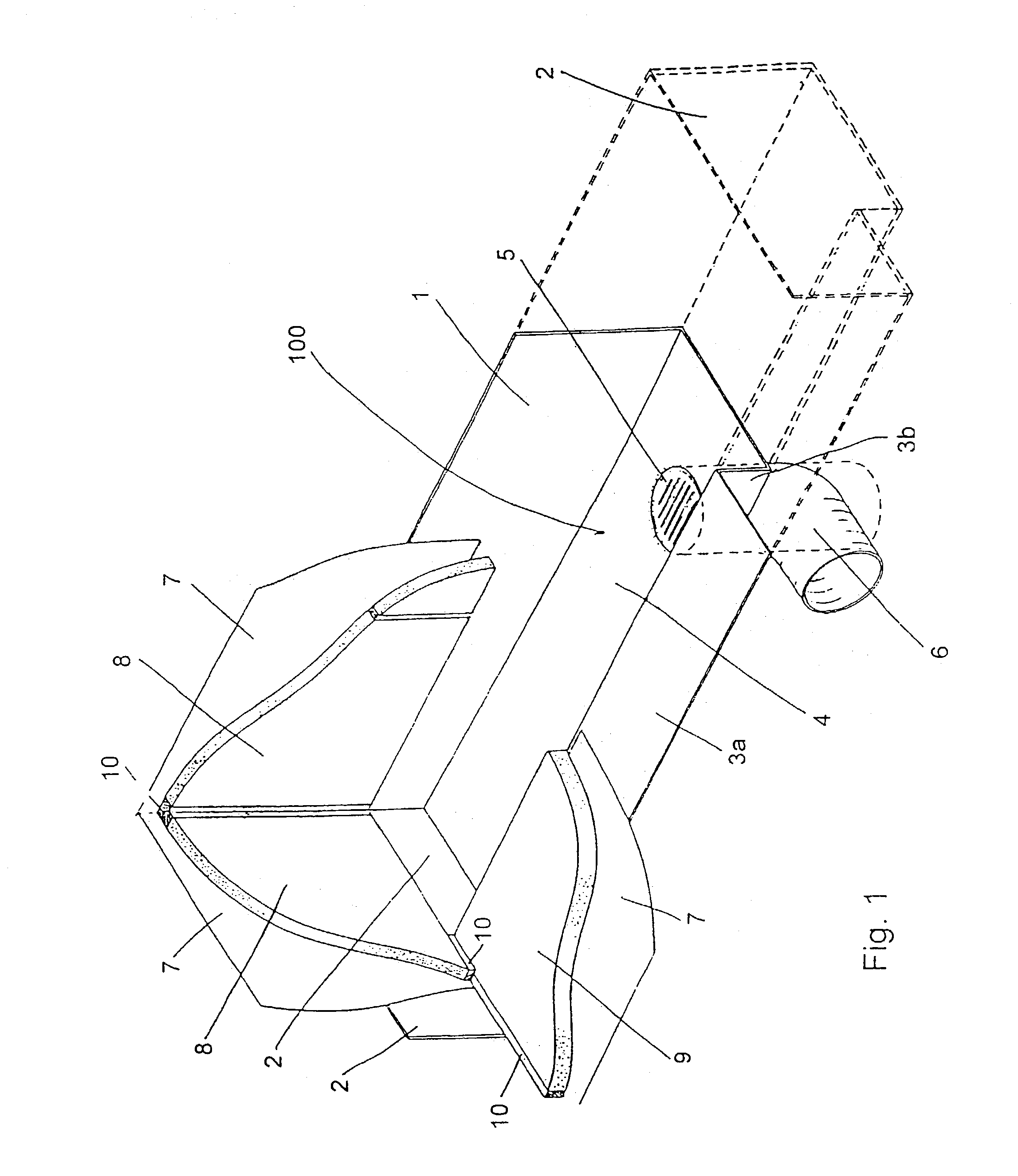
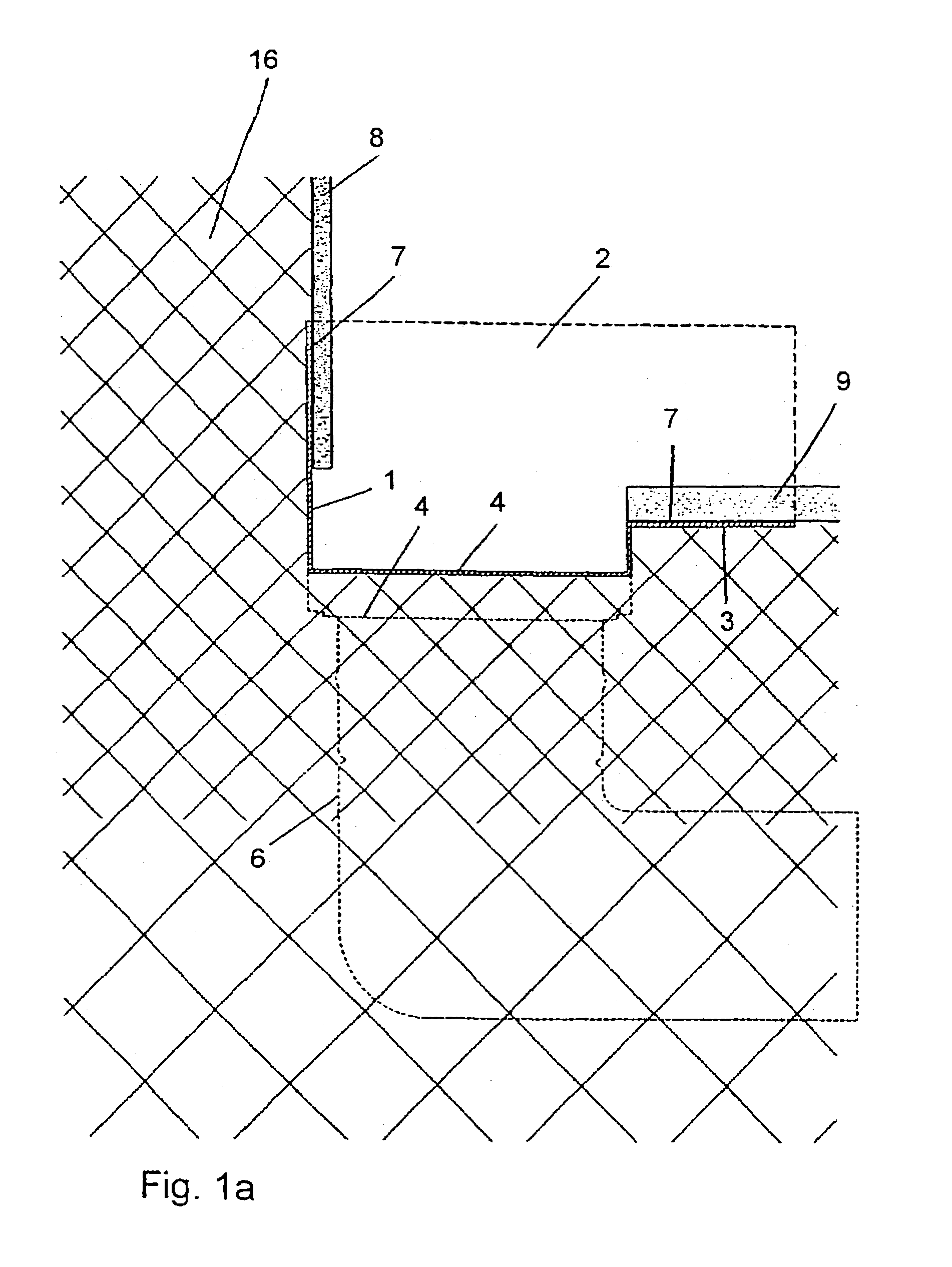
[0056]In the following the invention will be described in greater details and in particular different embodiments thereof will be addressed. The preferred embodiments will be addressed in connection with a bathroom. It should, however, be obvious for those skilled in the art, that the invention also is applicable to other kinds of rooms designed in such a manner that the walls and floor of the rooms are exposed to running water and wherein the water is to be drained.

[0057]In the following description, numerals used for identification of similar parts in different embodiments of the invention are the same in order to ease the understanding of the invention only.

[0058]Further scope of applicability of the present invention will become apparent from the detailed description given hereinafter. However, it should be understood that the detailed description and specific examples, while indicating preferred embodiments of the invention, are given by way of illustration only, since various ...


PUM


Abstract

A floor drain (100) comprising a bottom part (4) having at least one discharge opening (5), a front part being integral with the bottom part (4) and having a first part (3b) being inclined to said bottom part at an angle being at least 30°, such as at least 45°, preferably at least 60° more preferably at least 75° and even more preferably about 90° or at least 90° and having a flange part (3a) being horizontal or inclined to horizontal at an angle being less than 20° such as less than 17°, preferably less than 15°, such as less than 10°, more preferably less than 5°, tow side walls (2) integral with said bottom part and said first part, and a back part (1) being integral with said bottom part (4), said back part (1) extending vertically from the bottom part (4), through and above the plane defined by the flange part (3a).

Description

[0001]This is a nationalization of PCT / DK01 / 00203 filed Mar. 26, 2001 and published in English.[0002]The present invention relates to a floor drain, a building structure having such a floor drain and a method for installing such a floor drain in a building structure. The building structure is in preferred embodiments of the invention a bathroom or the like in which water, being splashed to the walls and floor, is drained from the room by the drain situated in the floor and connected to the sewer.BACKGROUND OF THE INVENTION [0003]A technical problem in connection with such rooms is that the building structure defining the room must be sealed in a fluid tight manner in order to avoid water from penetrating into the wall and floor construction, which if occurring often results in rot in the structure which in turn requires a very expensive reconstruction of the structure.[0004]While many—and excellent—solutions today exist for fluid tightening the walls and floor of such rooms no real ...

Claims


Application Information

Patent Timeline
Patent Type & Authority Patents(United States)
IPC IPC(8): E04B1/70E03C1/12E03F5/04
CPCE03F5/0406E03F5/0407E03F5/0408E03F2005/0418Y02A30/60
Inventor NIELSEN, CLAUS DYRE
Owner UNIDRAIN
Why Eureka
Try Eureka