FLADE gas turbine engine with counter-rotatable fans

a technology of gas turbine engines and fans, which is applied in the direction of positive displacement liquid engines, liquid fuel engines, piston pumps, etc., can solve the problem of engine weight reduction

Active Publication Date: 2007-07-24
GENERAL ELECTRIC CO
View PDF18 Cites 109 Cited by
  • Summary
  • Abstract
  • Description
  • Claims
  • Application Information

AI Technical Summary

Problems solved by technology

This significantly decreases the weight of the engine.
One issue regarding engine efficiency is the desirability of equalizing fan rotor torque between the counter-rotatable fans.

Method used


Image

  • FLADE gas turbine engine with counter-rotatable fans
  • FLADE gas turbine engine with counter-rotatable fans
  • FLADE gas turbine engine with counter-rotatable fans

Examples


Embodiment Construction

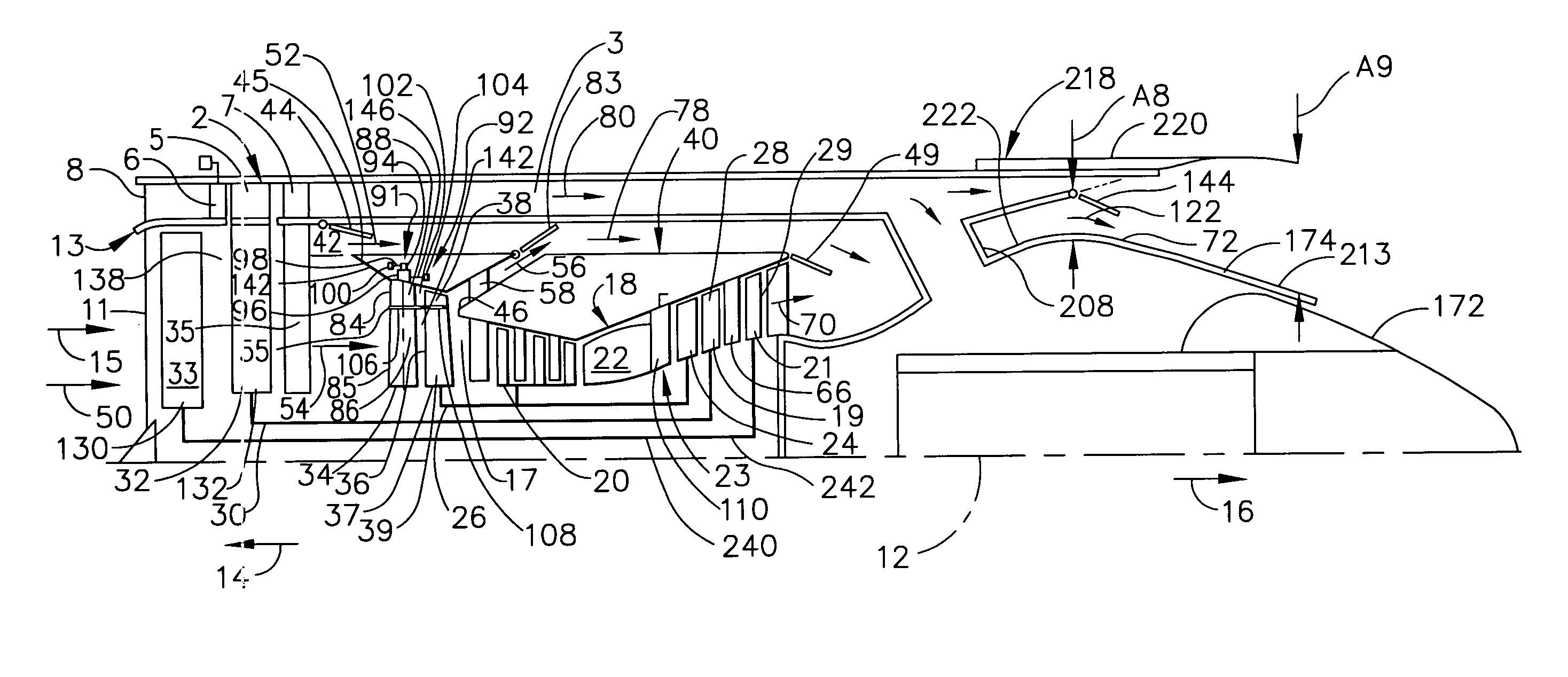
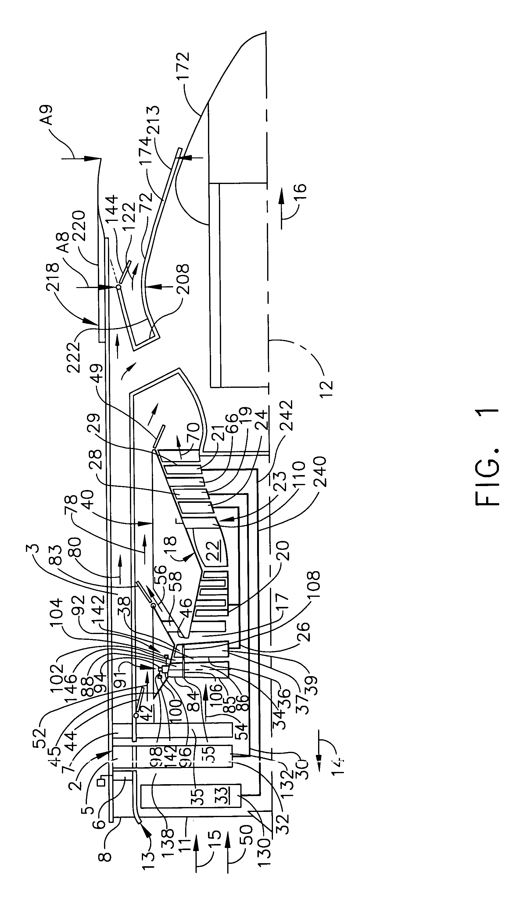
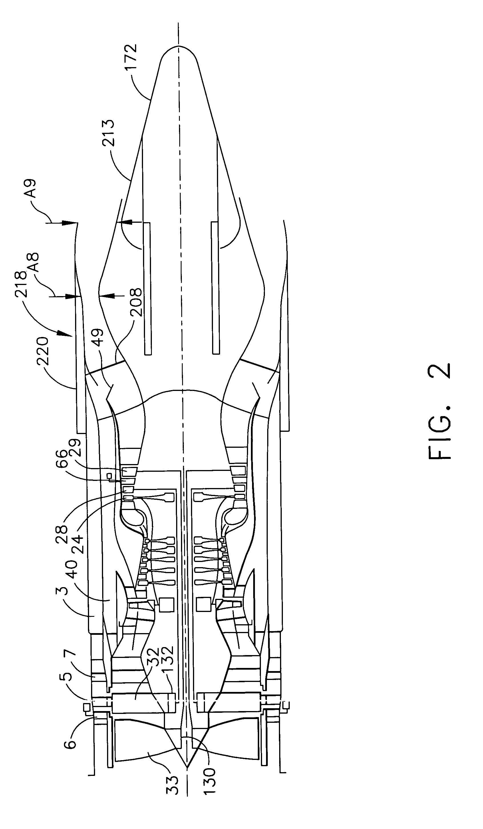
[0021]Illustrated in FIGS. 1–3 is a FLADE counter-rotatable fan aircraft gas turbine engine 1 having a fan inlet 11 leading to first and second counter-rotatable fans130 and 132. A FLADE fan 2 having at least one row of FLADE fan blades 5 disposed in a FLADE duct 3 through which FLADE airflow 80 is exhausted by the FLADE fan blades 5. The row of FLADE fan blades 5 is disposed radially outward of, operably connected to, and driven by one of the first or second counter-rotatable fans 130 and 132. In FIG. 1, the second fan 132 is illustrated as the FLADE fan having a row of FLADE fan blades 5 disposed between an axially forward row of variable first FLADE vanes 6 and an axially aft row of fixed second FLADE vanes 7. The FLADE fan 2 is disposed downstream of an annular FLADE inlet 8 to the FLADE duct 3. The FLADE inlet 8 and the fan inlet 11 in combination generally form a FLADE engine inlet 13 having a FLADE engine inlet area AI. Downstream and axially aft of the first and second count...


PUM


Abstract

An exemplary embodiment of a FLADE counter-rotating fan aircraft gas turbine engine includes at least one row of FLADE fan blades disposed radially outwardly of and drivingly connected to one of axially spaced-apart first and second counter-rotatable fans. A core engine located downstream and axially aft of the first and second counter-rotatable fans is circumscribed by a fan bypass duct downstream and axially aft of the first and second counter-rotatable fans. The row of FLADE fan blades radially extend across a FLADE duct circumscribed about the first and second counter-rotatable fans and the fan bypass duct. A second low pressure turbine is drivingly connected to the first counter-rotatable fan and a first low pressure turbine is drivingly connected to the second counter-rotatable fan.

Description

[0001]The Government has rights in this invention pursuant to Contract No. MDA972-01-3-0002 awarded by the Defense Advanced Research Projects Agency.BACKGROUND OF THE INVENTION[0002]1. Field of the Invention[0003]This invention relates to FLADE aircraft gas turbine engines and, more particularly, to such engines with counter-rotatable fans.[0004]2. Description of Related Art[0005]High performance variable cycle gas turbine engines are being designed because of their unique ability to operate efficiently at various thrust settings and flight speeds both subsonic and supersonic. An important feature of the variable cycle gas turbine engine which contributes to its high performance is its capability of maintaining a substantially constant inlet airflow as its thrust is varied. This feature leads to important performance advantages under less than full power engine settings or maximum thrust conditions, such as during subsonic cruise. Counter-rotating fan gas turbine engines have also b...

Claims


Application Information

Patent Timeline
Patent Type & Authority Patents(United States)
IPC IPC(8): F02K3/02F02C1/06F01D17/16F02C9/22F02K3/06F02K3/072F02K3/077F04D29/38F04D29/56
CPCF02K3/072F02K3/077Y02T50/671F05D2220/327Y02T50/60
Inventor GIFFIN, III, ROLLIN GEORGEJOHNSON, JAMES EDWARD
Owner GENERAL ELECTRIC CO
Why Eureka
Try Eureka