Elevator door system

a technology of elevator doors and doors, applied in the field of elevator doors, can solve the problems of affecting the operation of the elevator, the cost of constructing the machine room, and the structure required to support the weight of the machine room and the elevator equipment, and the cost of shading adjacent properties from sunlight, and the expense also includes the length of the hoistway

Inactive Publication Date: 2007-07-24
OTIS ELEVATOR CO
View PDF58 Cites 12 Cited by
  • Summary
  • Abstract
  • Description
  • Claims
  • Application Information

AI Technical Summary

Benefits of technology

[0007]A first advantage of the present invention is that the elevator system reduces the required reserved space between the top of the elevator car and the ceiling of the hoistway or the space between a bottom of the car and the floor.
[0008]A second advantage of the present invention is that the hoistway does not require additional space to accommodate the drive motor between the elevator car and a sidewall of the hoistway.

Problems solved by technology

Considerable expense is involved in the construction of an elevator hoistway and machine room.
The expense includes the cost of constructing the machine room, the structure required to support the weight of the machine room and elevator equipment, and the cost of shading adjacent properties from sunlight (e.g., sunshine laws in Japan and elsewhere).
The expense also includes the length of the hoistway.
However, this approach only results in shifting the clearance problem since additional space is required in the lower portion of the hoistway to accommodate the door operator.
A drawback with placing the door system on a side of the car is that additional space between the car and hoistway sidewall is necessary to accommodate rather bulky, conventional motors which drive the elevator car and hoistway doors.
Thus the additional side space required to accommodate the drive system detracts from any savings due to reducing the overhead space of the hoistway.

Method used


Image

  • Elevator door system
  • Elevator door system
  • Elevator door system

Examples


second embodiment

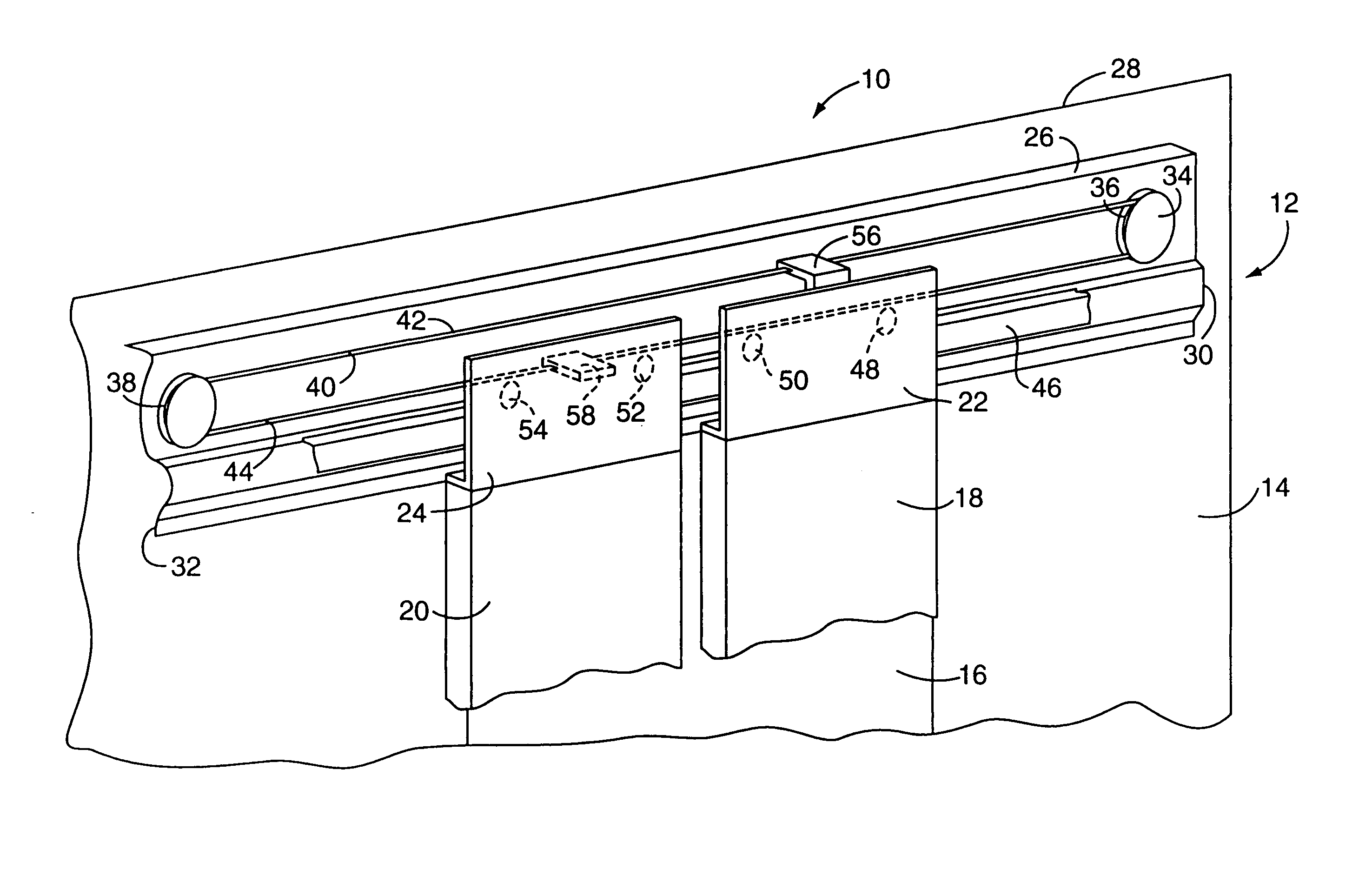
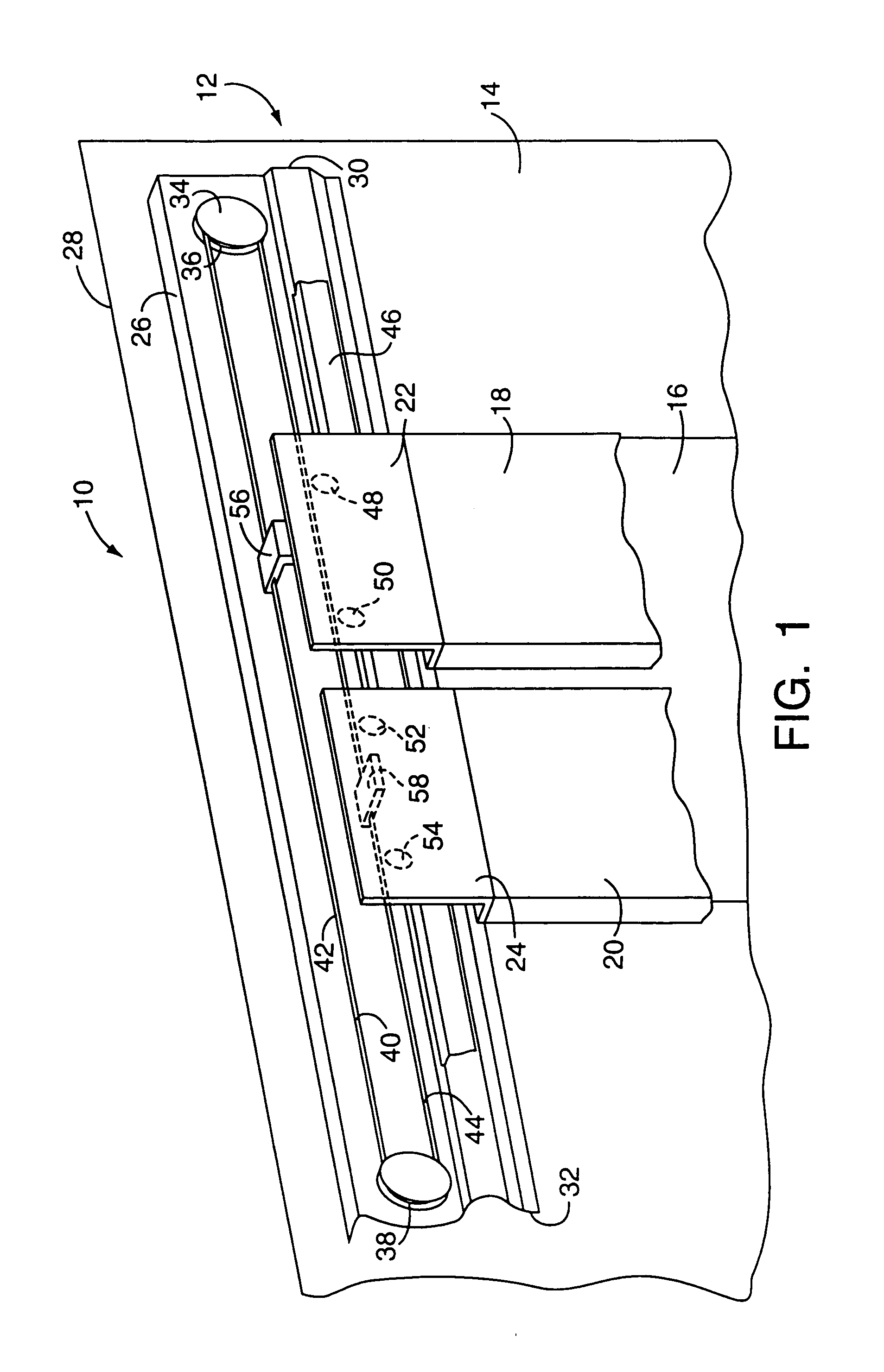
[0037]Turning now to FIG. 3, an elevator door system in accordance with the present invention is generally designated by the reference number 100. For simplicity of illustration, the system 100 does not show the pulley system for assisting in the movement of the elevator doors, such as, for example, the pulley system of FIG. 1 which includes the first and second sheaves 36, 38, the fixations 56, 58 and the rope 40.

[0038]The door system includes an elevator car 102 (shown in part) having a front face 104 defining a door opening (not shown). First and second doors 106, 108 respectively include first and second hangers 110, 112 projecting upwardly from a body of the doors for mounting the doors to the elevator car 102 over the door opening. As shown in FIG. 3, the hangers 110, 112 when mounted on the elevator car 102 are spaced frontwardly of the front face 104.

[0039]An elongated member or roller track 114 is mounted on either a header bracket or directly to the front face 104 of the e...

third embodiment

[0045]Turning now to FIG. 4, an elevator door system in accordance with the present invention is generally designated by the reference number 150. The elevator door system 150 includes at least one door having a hanger, such as the two doors 152, 152 with hangers 154, 154 shown in FIG. 4. A roller track 156 and a length of rope 158 fixed at each end are disposed above the roller track extend along a front face 160 of an elevator car. At least one track roller, such as two track rollers 162, 162, are coupled to the hanger 154 of each door 152 and rotatably engage an upper surface 163 of the roller track to support the door and to facilitate movement of the door between its open and closed positions. Further, a flat, drive motor 164 including a traction sheave 166 and at least one deflector roller, such as the two deflector rollers 168, 168, are coupled to the hanger 154 of each door, and rotatably engage the fixed rope 158. In operation, as each drive motor 164 is actuated and rotate...

fourth embodiment

[0046]With reference to FIGS. 5 and 6, an elevator door system in accordance with the present invention is generally designated by the reference number 200. For simplicity of illustration, the system 200 does not show the front face of the elevator car or the pulley system for assisting in the movement of the elevator doors, such as, for example, the pulley system of FIG. 1 which includes the first and second sheaves 36, 38, the fixations 56, 58 and the rope 40.

[0047]The door system 200 includes an elevator car (not shown) similar to that shown in the previous embodiments. At least one elevator door 202 includes a hanger 204 projecting upwardly from a body of the door for mounting the door to the elevator car over a door opening. The hanger 204 when mounted on the elevator car is spaced frontwardly of a front face of the elevator car. An upper, elongated member or upper roller track 206 is mounted on either a header bracket or directly to the front face of the elevator car below an ...


PUM


Abstract

An elevator door system includes an elevator car having a front face defining a door opening. At least one elevator door is coupled to the front face of the elevator car for movement between an open position exposing the door opening and a closed position covering the door opening. At least one drive motor is mounted on the front face of the elevator car and is disposed between a lower edge and an upper edge of the elevator car. The drive motor is drivingly coupled to the elevator door for moving the elevator door between the open and the closed positions.

Description

FIELD OF THE INVENTION[0001]The present invention relates generally to an elevator system, and more particularly to an elevator door system including a drive motor coupled to an elevator car and disposed below the ceiling of the elevator car.BACKGROUND OF THE INVENTION[0002]Considerable expense is involved in the construction of an elevator hoistway and machine room. The expense includes the cost of constructing the machine room, the structure required to support the weight of the machine room and elevator equipment, and the cost of shading adjacent properties from sunlight (e.g., sunshine laws in Japan and elsewhere). The expense also includes the length of the hoistway. Typically, local codes require a minimum clearance between the top of the elevator car at its highest position in the hoistway and the hoistway ceiling. Conventionally, the highest item on top of the elevator car is the door operator which is located on top of or projects partly above the elevator car ceiling. By e...

Claims


Application Information

Patent Timeline
Patent Type & Authority Patents(United States)
IPC IPC(8): B66B13/06B66B13/08E05F15/14E05F15/60
CPCB66B13/08E05F15/635E05F15/60E05Y2201/434E05Y2400/654E05Y2900/104E05Y2800/268E05Y2600/46E05Y2201/652E05Y2201/688
Inventor TONNA, CHRISTIAN G.SCHRODER-BRUMLOOP, HELMUTDURAND, CHRISTOPH
Owner OTIS ELEVATOR CO
Why Eureka
Try Eureka