Adjustable cassette for substrates

a cassette and substrate technology, applied in the field of cassettes, can solve the problems of increasing storage and transportation costs, and achieve the effect of easy adjustment of the distance between the supporting walls

Active Publication Date: 2007-07-24
INNOLUX CORP
View PDF10 Cites 40 Cited by
  • Summary
  • Abstract
  • Description
  • Claims
  • Application Information

AI Technical Summary

Benefits of technology

[0010]The advantage of the invention is that a distance between the supporting walls can be easily adjusted by pivoting the pivot elements. Thus the space defined by the chassis and the supporting walls is adjusted accordingly, in order to accommodate substrates of a particular size. Once the pivot elements are set in position, they are kept in position by protrusive bottom ends of shafts of the pivot elements being engaged in locating holes of bottom locating plates, and latch pins of the shafts being engaged in selected latch slots of top locating plates. The cassette is adaptable for use with substrates of various sizes simply by pivoting the pivot elements.

Problems solved by technology

This increases the cost of storage and transportation.

Method used


Image

  • Adjustable cassette for substrates
  • Adjustable cassette for substrates
  • Adjustable cassette for substrates

Examples


first embodiment

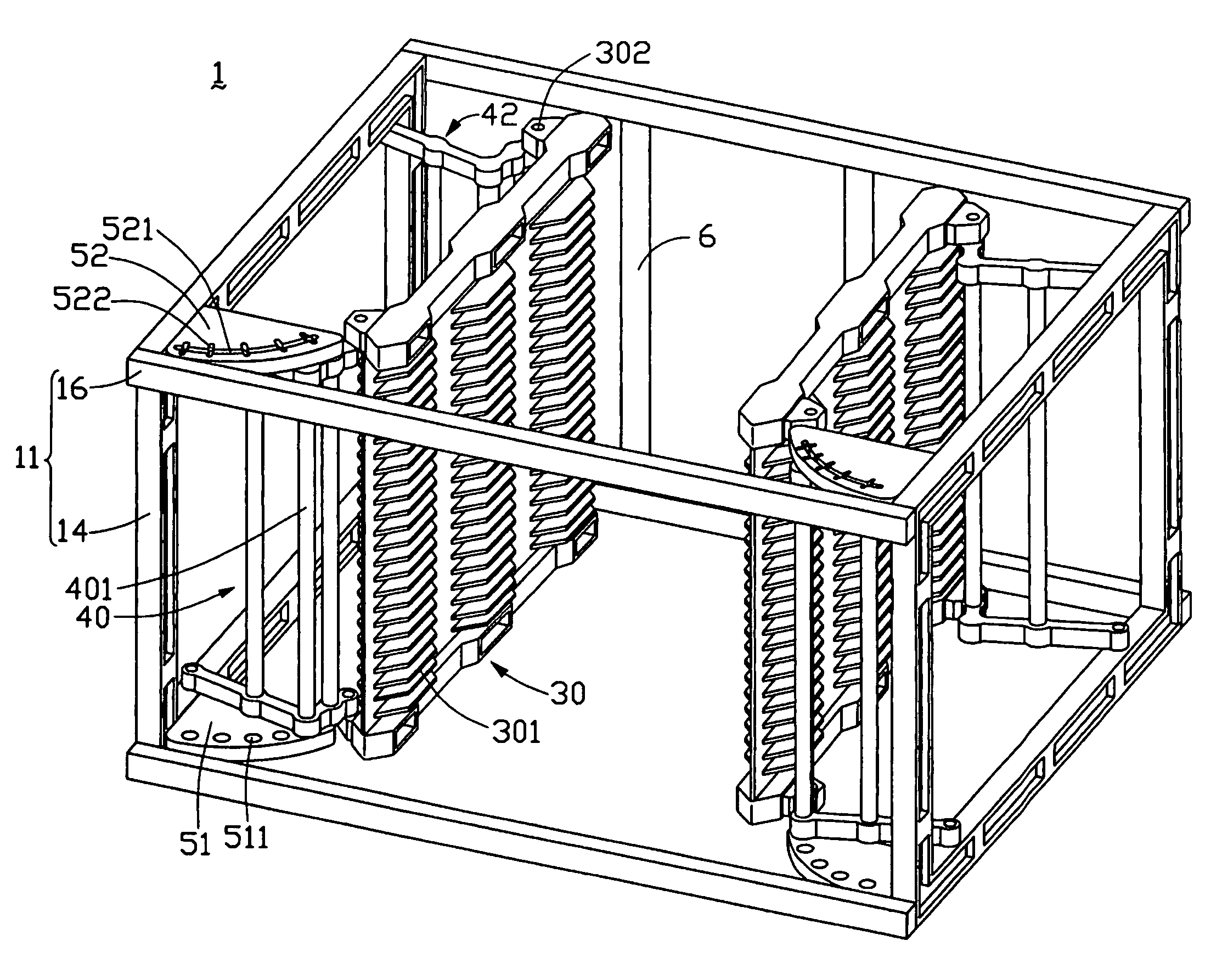
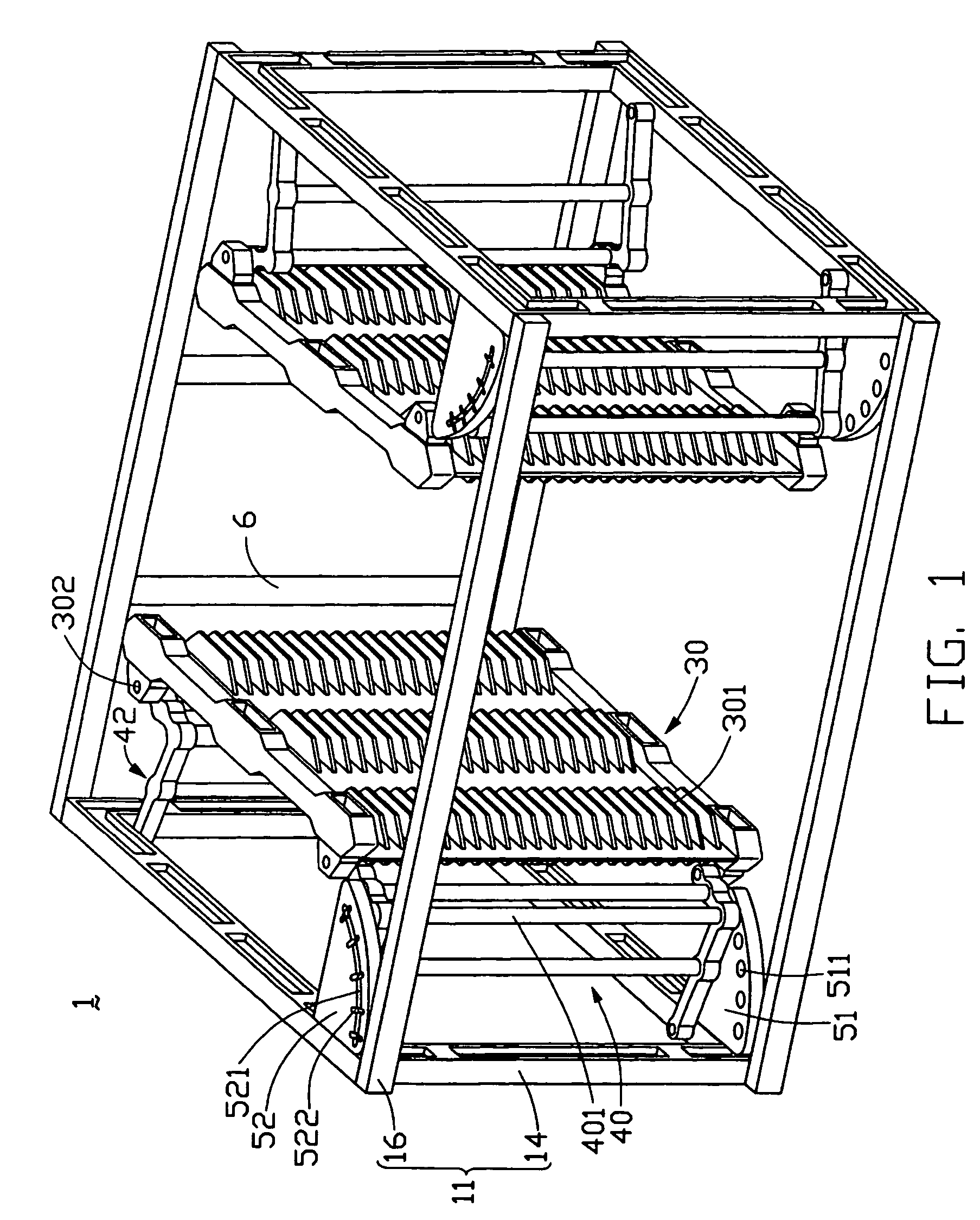
[0017]Referring to FIGS. 1 and 2, a cassette 1 in accordance with the present invention is for holding and transporting substrates. The cassette 1 includes a chassis 11, a pair of first locating plates 51, a pair of second locating plates 52, a pair of supporting walls 30, a pair of first pivot elements 40, and a pair of second pivot elements 42.

[0018]The chassis 11 includes a pair of rectangular frames 14, a plurality of connection members 16, and one or more stop rods 6. The frames 14 are spaced opposite from each other, and are interconnected by the connection members 16. The frames 14 have a plurality of pivot holes 17 defined therein. The stop rods 6 are arranged between two of the connection members 16 at a back side of the chassis 11.

[0019]The first locating plates 51 are respectively fixed to bottom sides of the frames 14, at front corners thereof. Each of the first locating plates 51 is semi-segment shaped, and defines a plurality of locating holes 511 therein. The locating...

second embodiment

[0026]Referring also to FIG. 3, in the second embodiment, a housing 18 interconnects the frames 14 instead of the connection members 16. The housing 18 has a front opening (not labeled) for the substrates to be inserted into the cassette 1.

[0027]In summary, the advantage of the described embodiments is that the distance between the supporting walls 30 can be easily adjusted by pivoting the pivot elements 40, 42. Thus said space defined by the chassis 11 and the first and second supporting walls 30 is adjusted accordingly, in order to accommodate substrates of a particular size. Once the pivot elements 40, 42 are set in position, they are kept in position by the protrusive bottom ends 4012 of the shafts 401 being engaged in the locating holes 511, and the latch pins 523 of the shafts 401 being engaged in the selected latch slots 522. The cassette 1 is adaptable for use with substrates of various sizes simply by pivoting the pivot elements 40, 42.


PUM

PropertyMeasurementUnit
distanceaaaaaaaaaa
structureaaaaaaaaaa
sizeaaaaaaaaaa

Abstract

A cassette (1) for holding and transporting substrates includes a chassis (11), a pair of supporting walls (30) facing each other, a pair of first pivot elements (40), and a pair of second pivot elements (42). The first and second pivot elements are pivotally connected to the chassis and supporting walls, respectively. Each of the supporting walls includes a plurality of supporting members (301) protruding inwardly therefrom. The chassis and the supporting walls define a space for accommodating the substrates on the supporting members. A distance between the supporting walls can be easily adjusted by pivoting the pivot elements. Thus the space defined by the chassis and the supporting walls is adjusted accordingly, in order to accommodate substrates of a particular size. The cassette is adaptable for use with substrates of various sizes simply by pivoting the pivot elements.

Description

BACKGROUND OF THE INVENTION[0001]1. Field of the Invention[0002]The present invention relates to a cassette for holding and transporting a plurality of substrates, particularly substrates such as liquid crystal panels.[0003]2. Prior Art[0004]Nowadays, various kinds of substrates including glass substrates are extensively used in the manufacturing of LCDs (Liquid Crystal Displays), plasma displays and hybrid ICs (Integrated Circuits). In general, the substrates are loaded into a substrate cassette for storage or transportation. The cassette can conveniently hold a plurality of the substrates. This kind of means is in widespread use for carrying a plurality of substrates between fabrication stations in a factory or between factories.[0005]A conventional cassette is shown in FIG. 4. The cassette 10 includes a top plate 2, a bottom plate 12, and two side plates 4 interconnecting the top plate 2 and the bottom plate 12. The side plates 4 have a plurality of parallel supporting members 8 ...

Claims


Application Information

Patent Timeline
Patent Type & Authority Patents(United States)
IPC IPC(8): A47G19/08A47B57/10A47B81/00G11B23/023
CPCA47B57/10A47B81/00G11B23/0236
Inventor CHUANG, CHENGDOULDENG, CHIEN-SUNGYANG, HUNG-WEN
Owner INNOLUX CORP
Why Eureka
Try Eureka